
Electrical plug connector for a safety restraint system

a technology of safety restraint system and plug connector, which is applied in the direction of coupling contact member, coupling device connection, incorrect coupling prevention, etc., can solve the problem of increasing contact pressure under constant contact force, and achieve automatic separation of contact between cutting edges

Active Publication Date: 2017-10-03
APTIV TECH LTD
View PDF7 Cites 2 Cited by
  • Summary
  • Abstract
  • Description
  • Claims
  • Application Information

AI Technical Summary

Benefits of technology

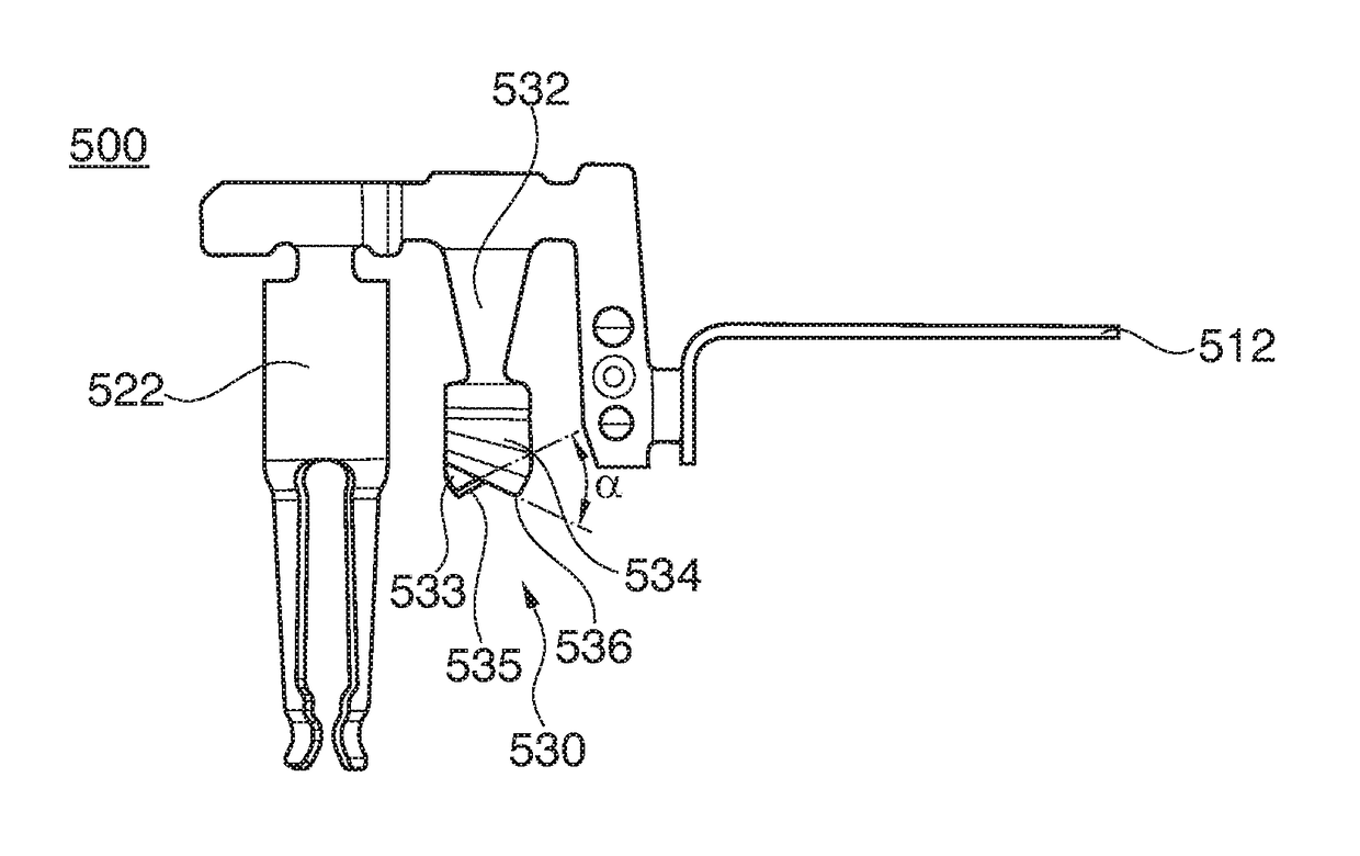
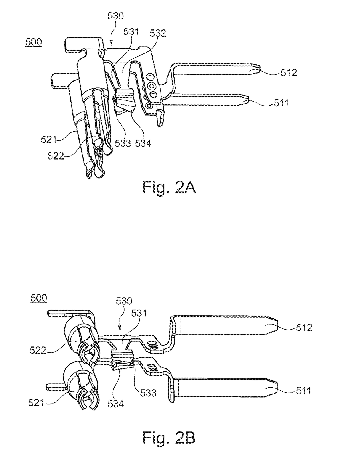
[0015]The cutting edges of the contact blades are preferably sharp edges. At least one of the cutting edges, preferably both, include an included angle of less than 90°, more preferable an included angle of less than 70° and even more preferable an included angle of less than 60°. As it is known from knife geometry, the edge angle of a blade is the angle between the blade center and the blade side surface, whereas the included angle is the angle between both blade sides, i.e. formed by the two adjacent surfaces of the blade that form the edge. It has to be noted, that the cutting edge can alternatively be provided with a radius or a phase. These cutting edges allow a relatively small contact area, compared to conventional shorting clips having e.g. contact tongues, since the cutting edges are arranged such that one edge cuts the other. The term “cutting” has to be understood as abutting the edges across each other, wherein preferably a microscopic cut or notch is driven into at least one of the cutting edges. This cutting improves the electrical contact between the contact blades, since the electrical resistance of the contact can be reduced, e.g. by cutting through residual layers of plastic, oxides or the like. Further, the relatively small contact area leads to an increase in contact pressure under constant contact force. A contact force is e.g. applied due to the preload of the contact blades that are preferably formed as preloaded springs.
[0020]Preferably, the cutting edges of the at least two contact blades are punched edges, having preferably at least one punching burr. Punched edges, having preferably the punching burr provide sharp edges that allow very small contact areas. Thus the contact pressure can be significantly increased under constant contact force. Further, the cutting can be improved, so that the electrical resistance of the contact can be reduced. Further, by applying high contact pressures, the electrical contact is less prone to being separated by vibrations or the like. Preferably, the contact area of the contact between the at least two edges is smaller than 1 mm2, preferably smaller than 0.5 mm2 and most preferably smaller than 0.1 mm2. These contact areas have shown two provide an increased contact condition between the cutting edges.
[0021]Preferably, at least one terminal and the respective contact blade are integrally formed as one part and even more preferably each contact blade is integrally formed with a respective one of the at least two contact terminals, wherein the integrally formed part is preferably made of a copper alloy. By integrally forming the terminal and the respective contact blade, manufacturing costs can be reduced and the number of parts to be handled during the assembly of the connector can be reduced. Thus, costs can be effectively minimized. Further, a copper alloy provides good electrical properties and a rigidity that allows the cutting of the cutting edges.
[0022]Preferably, the contact blades are not gold plated. Due to the geometry of the cutting edges, a plating, such as gold plating is no longer necessary, since the cutting edges are less prone to residual layers, as described above, and the contact pressure between the cutting plates is significantly increased.
[0023]Preferably, the cutting edges of the at least two contact blades are configured to execute a relative cutting movement to each other, during establishing the electrical contact between the cutting edges. This cutting movement results in that one cutting edge scratches over the other cutting edge, so that possible contaminants or residual layers can be removed. Thus, the electrical contact and in particular the electrical conductivity of the contact can be increased and the electrical resistance of the contact can be reduced. Preferably, the cutting edges of the at least two contact blades are configured to at least partly remove residual layers deposited on the cutting edges, in order to improve the electrical contact.
[0028]The object is further solved by an electrical connector system including a plug connector and a corresponding counter connector, wherein the plug connector includes a shorting clip as described above. This electrical connector system allows the monitoring of the correct coupled condition of the corresponding counter connector and the plug connector and further the short circuiting of the terminals of the plug connector.

Problems solved by technology

Further, the relatively small contact area leads to an increase in contact pressure under constant contact force.

Method used


Image

  • Electrical plug connector for a safety restraint system
  • Electrical plug connector for a safety restraint system
  • Electrical plug connector for a safety restraint system

Examples


Embodiment Construction

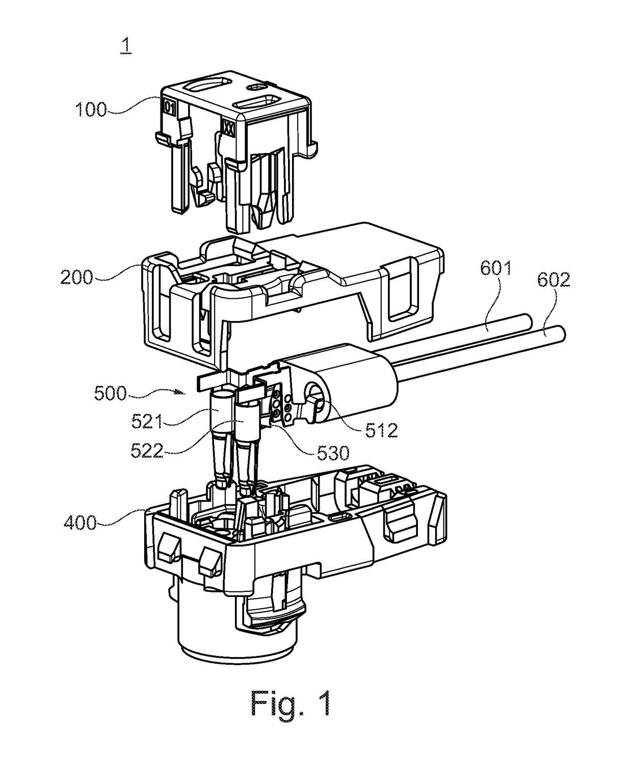
[0033]FIG. 1 shows a non-limiting example of an electrical plug connector, hereinafter referred to the plug connector 1 for a safety restraint system, preferably for an airbag ignition system. The plug connector 1 includes a housing, wherein the housing includes at least two parts, a main part 400 and a cover 200. The cover 200 is configured to receive a terminal assembly 500, including at least 2 terminals 521, 522. The two terminals 521, 522 are configured to be connected with corresponding pins of a corresponding counter connector. The terminal assembly 500 further includes a shorting clip 530. The shorting clip 530 is configured to short circuit the at least two contact terminals 521, 522 in an uncoupled or an incorrectly coupled condition of the plug connector. Further, a welding or soldering member 511, 512 is configured to be welded or soldered to a corresponding signal line 601, 602. Other suitable electrically conductive connecting methods are also possible. Further, the pl...


PUM


Abstract

The present invention relates to an electrical plug connector for a safety restraint system, preferably for an airbag ignition system. The plug connector includes at least two contact terminals assigned to the plug connector and a shorting clip that is configured to short-circuit the at least two contact terminals in an uncoupled or incorrectly coupled condition of the plug connector. The shorting clip includes at least two contact blades. Each contact blade is electrically connected with one of the at least two contact terminals. Each of the contact blades includes at least one cutting edge. The cutting edges contact each other such that one edge cuts the other when the plug connector is in an uncoupled or incorrectly coupled condition.

Description

CROSS-REFERENCE TO RELATED APPLICATION[0001]This application claims the benefit under 35 U.S.C. §119(a) of Patent Application No. 15176757.1 filed in the European Patent Office (EPO) on Jul. 15, 2015, the entire disclosure of which is hereby incorporated by reference.TECHNICAL FIELD OF THE INVENTION[0002]The invention relates to an electrical plug connector for a safety restraint system, preferably for an airbag ignition system and in particular to plug connectors including at least two terminals, with which it is possible to electrically or electronically monitor the correct coupling of the plug connector with a suitable counter connector.BACKGROUND OF THE INVENTION[0003]Passenger cars have nowadays a number of safety restraint systems, such as seat belts pretensions or airbags, as e.g. front and side airbags, which serve to cushion or limit the impact of a passenger with for example interior parts of passenger cars in case of an accident. Deceleration sensors in the passenger vehi...

Claims


Application Information

Patent Timeline
Patent Type & Authority Patents(United States)
IPC IPC(8): H01R29/00H01R13/71H01R13/641H01R13/703H01R13/642
CPCH01R13/71H01R13/641H01R13/642H01R13/7033H01R13/02H01R29/00H01R43/26H01R2201/26
Inventor NUETZEL, PETERGUNREBEN, MICHAELREGNIER, VINCENTODOERFER, FRANK
Owner APTIV TECH LTD
Learn More