
Variable speed control apparatus for automotive vehicles

a technology of variable speed and control apparatus, which is applied in the direction of cycle, transportation and packaging, gearing, etc., can solve the problems of unfavorable type and the inability to make changes in the variable speed ratio over a wide range of engine revolutions

Inactive Publication Date: 2002-03-07
BANDO CHEM IND LTD
View PDF0 Cites 20 Cited by
  • Summary
  • Abstract
  • Description
  • Claims
  • Application Information

AI Technical Summary

Benefits of technology

[0019] That is, generally, initial tension working on a belt splits into a tight side tension and a slack side tension by rotational torque that is input to a driving pulley, and power transmission from the driving pulley to a driven pulley is carried out by the difference between these tensions. However, belt pressing forces at the pulleys become approximately the same in a static state in which the pulleys do not rotate and in a light load state in which the transmission load is small even when the pulleys are rotating. On the contrary, when the transmission load increases, the belt pressing force on the driving pulley side becomes greater than that on the driven pulley side at all times by the change in tension distribution in the belt, therefore producing a difference therebetween. In accordance with the present invention, the cam mechanism is disposed on the rear face side of the movable sheave of each pulley so that the movable sheave travels in the shaft direction by the relative rotation between the rotary and stationary cams. Belt pressing forces occurring in the pulleys are offset, and by application of a force greater than such a pressing force difference, it becomes possible to perform variable speed operation. Accordingly, as described above, it is sufficient that the variable speed operation force is one in excess of the difference between belt pressing forces occurring in the pulleys. Therefore, the variable speed operation force is reduced considerably not only during low load but also during high load, thereby making it possible to make the control motor small in output and in size.
[0020] Additionally, at that time, it is arranged such that transmitting a belt pressing force occurring in one of the pulleys as a belt pressing force occurring in the other pulley is carried out by the cam mechanisms disposed on the rear face side of the movable sheaves of the pulleys, so that the belt pressing force of each pulley can efficiently be converted into a torque for causing the cams of the cam mechanisms to rotate relatively with each other, and further its power transmission line is short and the sliding resistance becomes extremely small. Therefore, the variable speed operation force can be reduced to a further extent.
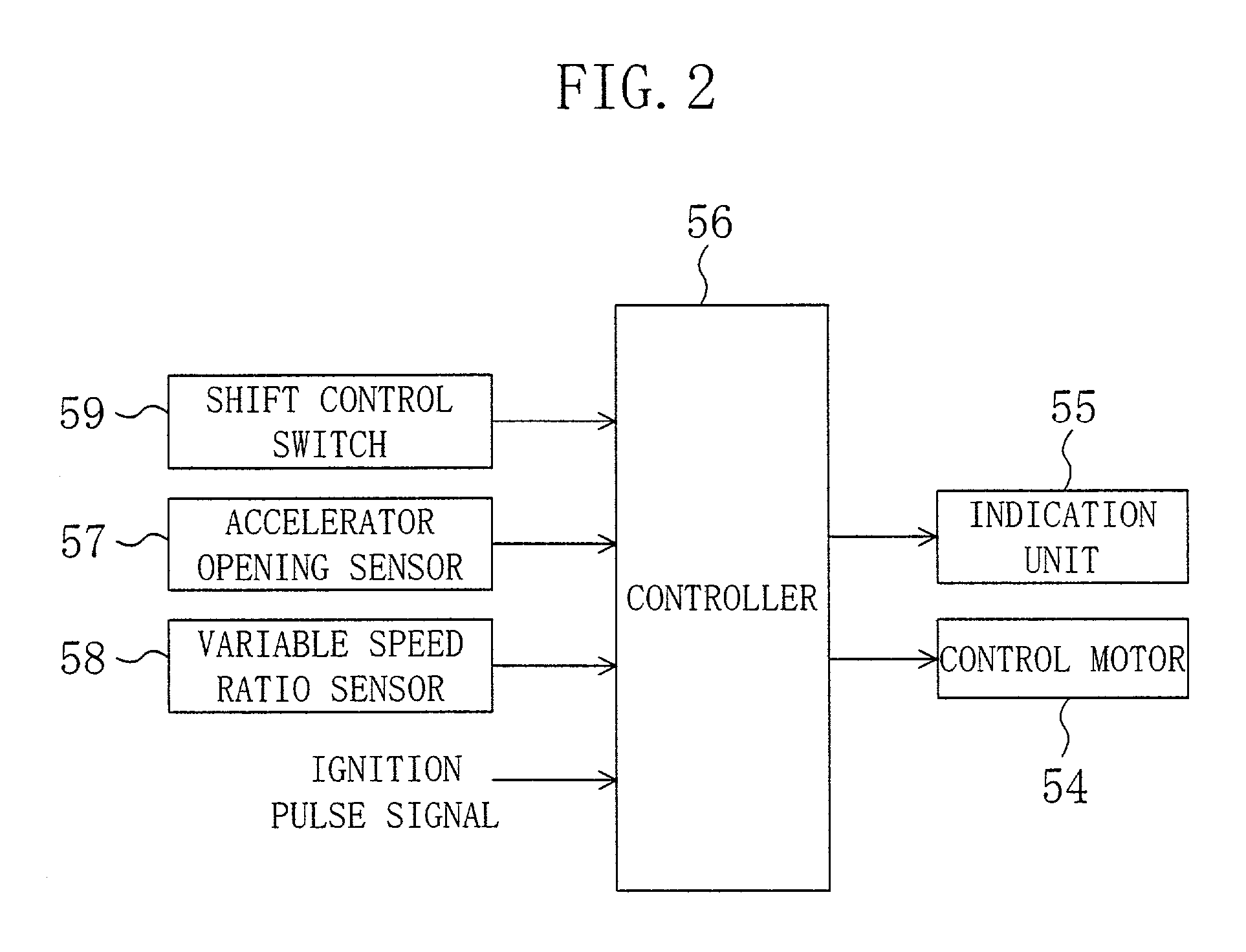
[0021] Furthermore, the shift control switch is operated by a vehicle driver, and based on a control signal from the shift control switch, the variable speed mode by the infinitely variable speed transmission is shifted between two modes, i.e., the semi- and full-automatic 
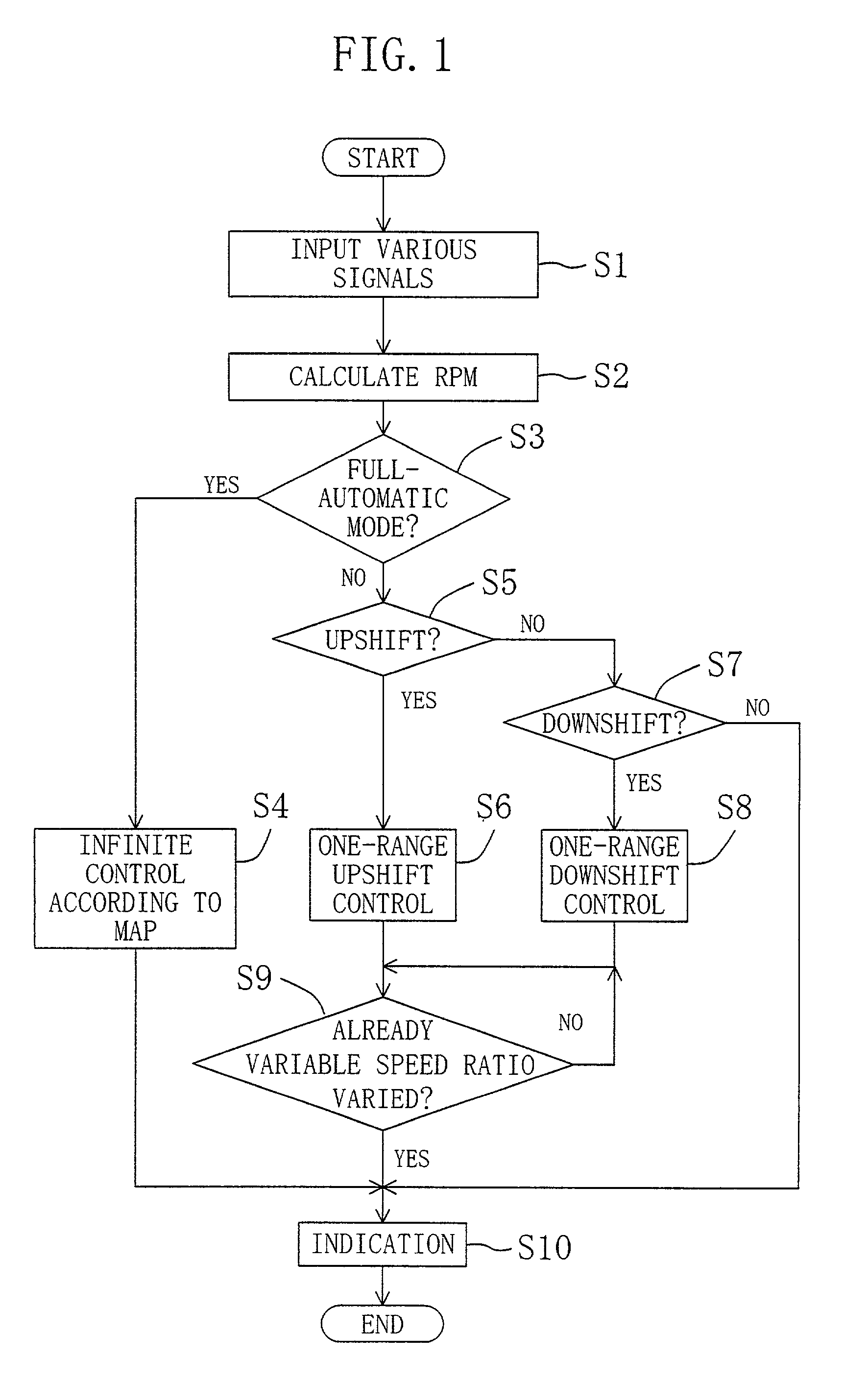
modes. When shifted to the semi-automatic mode, the variable speed ratio of the infinitely variable speed transmission is shifted to a selected one of a plurality of preset variable speed ratios, whereas, when shifted to the full-automatic mode, the variable speed ratio of the infinitely variable speed transmission is controlled so as to vary infinitely. As described above, the variable speed mode is shifted between the two modes (the semi- and full-automatic modes). This makes it possible to perform control so that the variable speed ratio of the infinitely variable speed transmission can be varied automatically infinitely. Besides, it is possible to use the infinitely variable speed transmission as if it were a finitely variable transmission. This provides better driving convenience for vehicle sports traveling et cetera, thereby satisfying the likes of a vehicle driver.
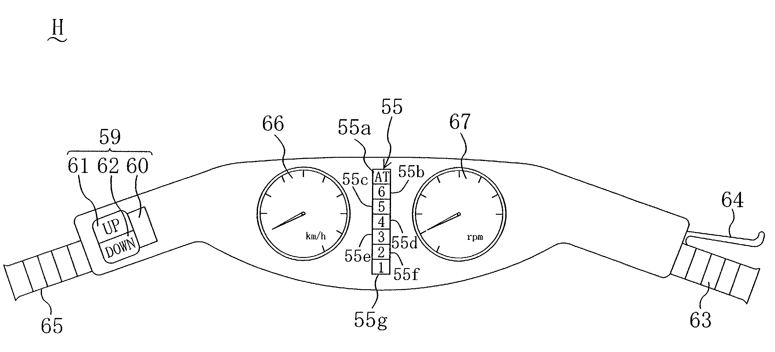
[0023] In such a case, it may be arranged such that the shift control switch is positioned at one end of a handle of the vehicle opposite to the other end at which an accelerator grip is provided and the shift control switch is operated by one of hands of a driver of the vehicle opposite to the other hand which performs accelerator operations. As a result of such arrangement, the shift control switch is operated by a hand different from the hand for acceleration operations, therefore ensuring that the occurrence of shift control switch maloperation is avoided.
[0024] An indicator means for indicating variable speed positions in the full- and semi-automatic modes by the control means may be provided. Such arrangement allows the driver to easily identify a shift of the variable speed mode, and a variable speed position in the semi-automatic mode, thereby improving driving convenience.

Problems solved by technology

However, such a belt infinitely variable speed transmission of the weight roller type unadvantageously exhibits the following variable speed characteristics.
Because of this, it is impossible to make changes in variable speed ratio over a wide range of engine revolutions.
In such a case, however, the load for variable speed shifting is large, therefore giving rise to the requirement for the provision of a large-size motor to perform quick variable speed shifting.

Method used


Image

  • Variable speed control apparatus for automotive vehicles
  • Variable speed control apparatus for automotive vehicles
  • Variable speed control apparatus for automotive vehicles

Examples


Embodiment Construction

[0033] Hereinafter, an embodiment of the present invention will be described with reference to the accompanying drawings. Referring to FIG. 3, there is shown a belt infinitely variable speed transmission T according to an embodiment of the present invention. This infinitely variable speed transmission T is mounted on a motor cycle (motorbike). More specifically, the infinitely variable speed transmission T is disposed between an on-vehicle engine (not shown) and a rear wheel as a driving wheel (not shown either), that is, in a power transmission line on the way to the rear wheel through which engine rotational power is transmitted to the rear wheel.

[0034] The infinitely variable speed transmission T is of the clutch-containing type and has a casing 1 which is laterally divided into two sections. Formed concavely in a front portion (an upper part in FIG. 3) of a left side wall of the casing 1 is an input shaft receiving hole 2. An output shaft receiving hole 3 is formed concavely in ...


PUM


Abstract

The variable speed shifting of an infinitely variable speed transmission T mounted on a motor cycle is carried out by a small-sized control motor 54 and the infinitely variable speed transmission T can be shifted also to a finite variable speed mode for satisfying the likes and needs of a rider. More specifically, movable sheaves 13 and 18 of driving and driven pulleys 11 and 16 comprised of variable speed pulleys are driven by cam mechanisms 30 and 40 interlocked by a linkage mechanism 49. The control motor 54 for operating the linkage mechanism 49 and a controller 56 for controlling the control motor 54 are provided. Based on a control signal from a shift control switch 59 which is operated by the rider of the motor cycle, the controller 56 allows the variable speed mode of the infinitely variable speed transmission T to shift between two different modes, i.e., a semi-automatic mode in which the variable speed ratio of the infinitely variable speed transmission T is shifted to a selected one of a plurality of preset variable speed ratios and a full-automatic mode in which the variable speed ratio is varied infinitely.

Description

[0001] 1. Technical Field of the Invention[0002] The present invention relates to a variable speed control apparatus for automotive vehicles having a belt infinitely variable speed transmission disposed in a power transmission line between an on-vehicle engine and a driving wheel.[0003] 2. Background Art[0004] A conventional belt infinitely variable speed transmission has been known in the art which comprises a variable speed pulley mechanism. The variable speed pulley mechanism includes variable speed pulleys and a V-belt. Each variable speed pulley has a stationary and a movable sheave. The stationary and movable sheaves of one of the variable speed pulleys are positioned on one of a pair of rotational shafts disposed in parallel with each other, whereas the stationary and movable sheaves of the other variable speed pulley are positioned on the other rotational shaft. More specifically, the stationary sheave is rigidly fixed to the rotational shaft in such a manner that it is rota...

Claims


Application Information

Patent Timeline
IPC IPC(8): F16H61/04F16H7/12F16H9/04F16H59/08F16H61/662F16H63/06
CPCF16H7/1281F16H61/66254F16H61/66272F16H63/062F16H63/067F16H2061/6616F16H9/04
Inventor MIYATA, HIROFUMI
Owner BANDO CHEM IND LTD
Learn More