Light controlling device using liquid crystal and method of producing the same
- Summary
- Abstract
- Description
- Claims
- Application Information
AI Technical Summary
Benefits of technology
Problems solved by technology
Method used
Image
Examples
second embodiment
[0098] Referring next to FIGS. 7 and 8, description will be given of a light controlling device according to a
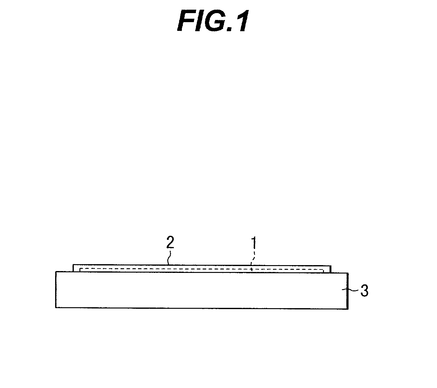
[0099] FIG. 7 schematically shows a cross section of a light controlling device 60 of the embodiment. In FIG. 7, the same constituent components as those shown in FIG. 1 or 5 are assigned with the same reference numerals, and description thereof will be avoided.
[0100] As can be seen by comparing FIG. 7 with FIG. 5, the optical controlling device 60 differs in structure from the optical controlling device 50 of the first embodiment in that a non-treated alignment film 2 is formed on one of the transparent substrates 3 of the cell container 30 and the cell container 30 is filled with liquid crystal 40a containing a chiral agent (e.g., S-811 or ZLI-3786 manufactured by Merck Ltd.). Excepting these points, the optical controlling device 60 is the same in structure as the optical controlling device 50 of the first embodiment.
[0101] The chiral agent is added to the liquid crystal ...
first embodiment
[0103] In the light controlling device 60 produced as above, the state of alignment of liquid-crystal molecules in a plane at a surface of the optically treated section of the treated alignment film 2a is substantially the same as that of liquid-crystal molecules in a plane at the surface of the optically treated section of the treated alignment film 2a in the light controlling device 50 of the On the other hand, the state of alignment of liquid-crystal molecules in a plane at a surface of the non-treated alignment film 2 is considerably different from that of the liquid-crystal molecules in a plane at the surface of the treated alignment film 2a.
[0104] FIG. 8 schematically shows the state of alignment of liquid-crystal molecules at the surface of the non-treated alignment film 2. Each arrow mark indicated by dotted lines indicates an alignment direction of the liquid-crystal molecules.
[0105] As shown in FIG. 8, liquid-crystal molecules at the surface are concentrically aligned abo...
third embodiment
[0112] Next, referring to FIGS. 9A and 9B, description will be given of a light controlling device according to a
[0113] FIG. 9A is a plan view schematically showing one of two transparent substrates 3 of the light controlling device 70 in the third embodiment.
[0114] FIG. 9B schematically shows a cross section of the light controlling device 70.
[0115] In FIGS. 9A and 9B, the same constituent components as those shown in FIG. 5 are assigned with the same reference numerals, and description thereof will be avoided.
[0116] The light controlling device 70 of the third embodiment is a light controlling device which can be used as a liquid-crystal lens. In the device 70, each transparent electrode pattern 1 includes one circular transparent electrode. An overall upper surface of the treated alignment film 2a is an optically treated section.
[0117] Excepting these points, the light controlling device 70 is constituted in the same way as for the light controlling device 50 of the first embodim...
PUM
 Abstract
Description
Claims
Application Information
 - R&D
- Intellectual Property
- Life Sciences
- Materials
- Tech Scout
- Unparalleled Data Quality
- Higher Quality Content
- 60% Fewer Hallucinations
Browse by: Latest US Patents, China's latest patents, Technical Efficacy Thesaurus, Application Domain, Technology Topic, Popular Technical Reports.
© 2025 PatSnap. All rights reserved.Legal|Privacy policy|Modern Slavery Act Transparency Statement|Sitemap|About US| Contact US: help@patsnap.com


