
Lens evaluation method and lens-evaluating apparatus

a technology of lens evaluation and lens axis, applied in the direction of optical apparatus testing, instruments, television systems, etc., can solve the problems of not being able to obtain an appropriate luminance value, unable to evaluate the mtf value of the respective projector and unable to compare the mtf value according to the same standard

Inactive Publication Date: 2002-04-18
SEIKO EPSON CORP
View PDF1 Cites 21 Cited by
  • Summary
  • Abstract
  • Description
  • Claims
  • Application Information

AI Technical Summary

Problems solved by technology

Further, in evaluating the resolution of the projection lens, since the image light irradiated from the projection lens to be projected on the screen tends to have the strongest intensity at the central portion to be grown weaker toward the peripheral portion thereof, even when the luminance value is obtained on a plurality of portions of the image projected on the screen, the MTF value cannot be evaluated according to the same standard.
Furthermore, when the brightness of the projected image differ according to the type of the projector, the MTF value of the respective projectors cannot be compared according to the same standard.
In the image sensor such as CCD, the relationship between the image light and the luminance value lacks proportionality where the output is too bright or too dark, thus failing to obtain an appropriate luminance value.

Method used


Image

  • Lens evaluation method and lens-evaluating apparatus
  • Lens evaluation method and lens-evaluating apparatus
  • Lens evaluation method and lens-evaluating apparatus

Examples


first embodiment

[0081] 1. First Embodiment

[0082] (1) Structure of Projector Installed with Projection Lens

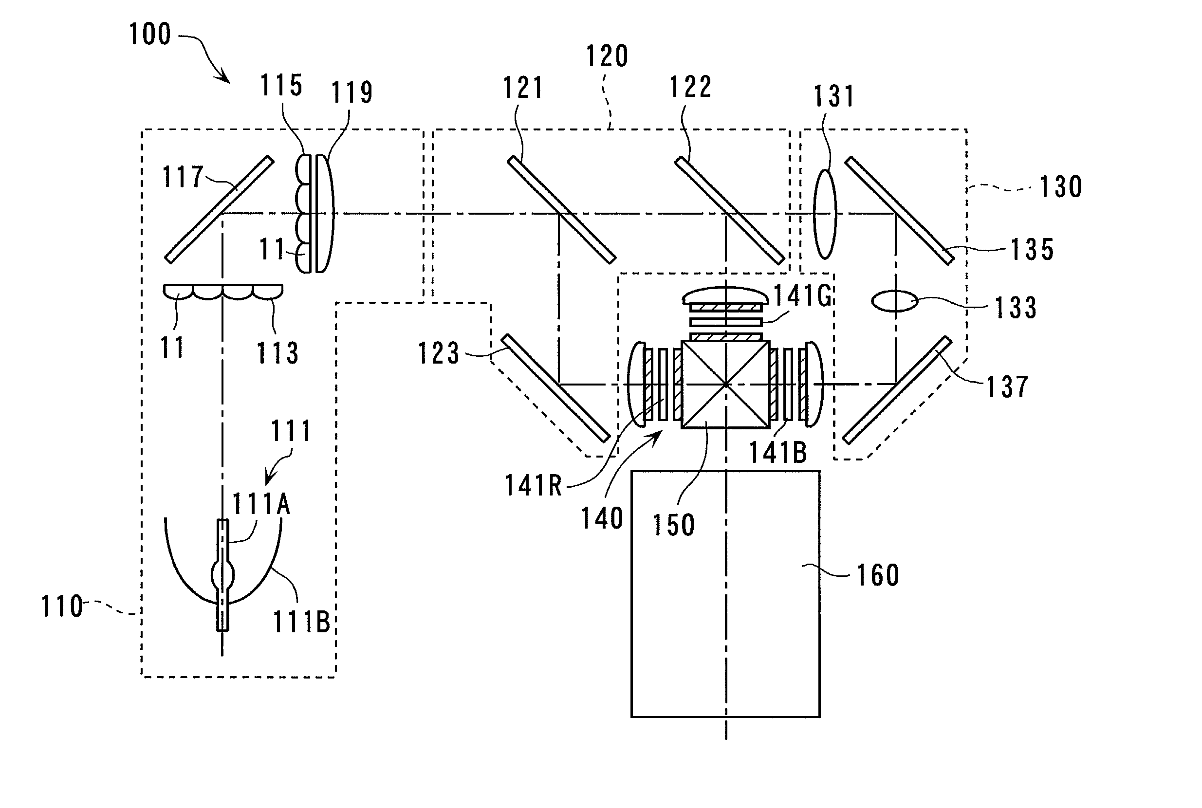
[0083] FIG. 4 shows a structure of a projector 100 for a projection lens to be installed. The projector 100 includes an integrator illuminating optical system 110, a color-separating optical system 120, a relay optical system 130, an electric optical device 140, a cross dichroic prism 150 as a color-combining optical system and a projection lens 160 as a projection optical system.

[0084] The integrator illumination optical system 110 has a light source 111 including light source lamp 111A and a reflector 111B, first lens array 113, second lens array 115, a reflection mirror 117 and a superposition lens 119. Irradiating direction of the light beam irradiated by the light source lamp 111A is aligned by the reflector 111B and is separated into a plurality of sub-beams by the first lens array 113, which is focused around the second lens array 115 after the irradiating direction is bent at a right an...

second embodiment

[0138] 2. Second Embodiment

[0139] Next, the second embodiment of the present invention will be described below.

[0140] In the following description, the same reference numeral will be attached to the same structure and components as the first embodiment and detailed explanation thereof will be omitted or simplified.

[0141] The evaluation apparatus of projection lens in the above first embodiment uses resolution-measuring test pattern 10A formed on the check sheet 450 to calculate the resolution evaluation value MTF of the projection lens 160 by the resolution evaluation calculator of the processing portion 610 composed of the background luminance value acquiring portion, the maximum luminance value acquiring portion and the minimum luminance value acquiring portion.

[0142] On the other hand, the evaluation apparatus of the projection lens according to the present embodiment differs from the above arrangement in that distortion aberration of the projection lens and distribution of in-pl...


PUM


Abstract

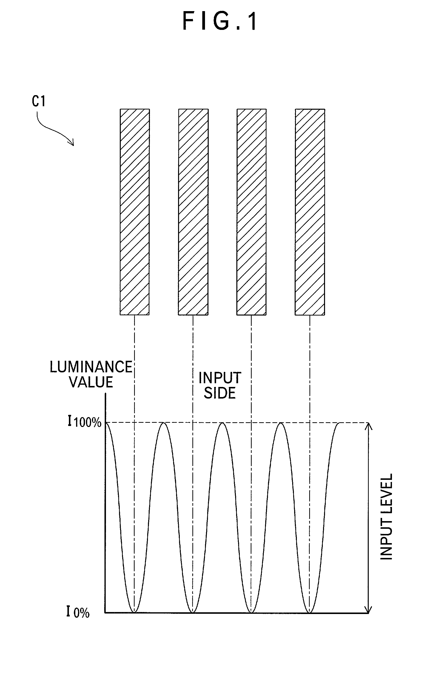
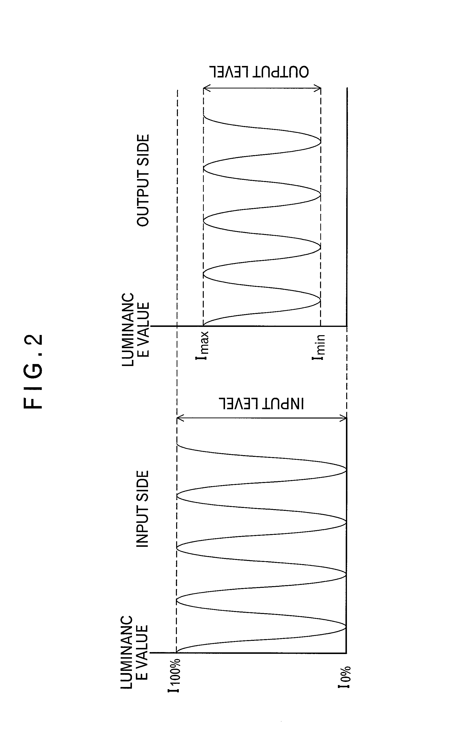
A lens evaluation method for calculating resolution evaluation value based on a detected luminance value in order to evaluate resolution of lens has a background luminance value acquiring step for acquiring a luminance value at a background part having no test pattern formed thereon, a maximum luminance value acquiring step for acquiring maximum luminance value in the test pattern image, a minimum luminance value acquiring step for acquiring minimum luminance value and an evaluation value calculating step for calculating a resolution evaluation value based on the luminance values obtained in the respective steps.

Description

[0001] 1 Field of the Invention[0002] The present invention relates to a lens evaluation method for evaluating resolution of a lens used for a projector, where an image light including test pattern for measuring resolution is irradiated on a screen through a projection lens to display the image of the resolution-measuring test pattern on the screen and the luminance of the displayed test pattern image is detected by an image import device using an image sensor to calculate a resolution evaluation value based on the detected luminance value, and a lens-evaluating apparatus for implementing the evaluation method.[0003] 2. Description of Related Art[0004] Conventionally, a projector including a plurality of liquid crystal panels for modulating a plurality of colors of light in accordance with image information, a cross dichroic prism for combining the color light modulated by the respective liquid crystal panels, and a projection lens for enlarging and projecting the light combined by ...

Claims


Application Information

Patent Timeline
IPC IPC(8): G01M11/02G02B7/02G02B7/04H04N17/04
CPCG01M11/0264G01M11/0242
Inventor KITABAYASHI, MASASHIKOJIMA, KOICHIUMEMURA, SHUNJI
Owner SEIKO EPSON CORP
Learn More