Lithographic projection apparatus, device manufacturing method, device manufactured thereby and gas composition

a technology of lithographic projection and projection apparatus, which is applied in the direction of printers, inorganic chemistry, photographic processes, etc., can solve the problems of insufficient to overcome errors, inability of second interferometric device to simultaneously account for pressure and temperature variations in the composition of the medium, and inability to absorb ligh

Inactive Publication Date: 2002-04-18
ASML NETHERLANDS BV
View PDF0 Cites 19 Cited by
  • Summary
  • Abstract
  • Description
  • Claims
  • Application Information

AI Technical Summary

Problems solved by technology

However, such wavelengths are strongly absorbed by normal atmospheric air leading to unacceptable loss of intensity as the beam traverses the apparatus.
However, this second interferometric device cannot simultaneously account for the variations in pressure and temperature and in the composition of the medium.
Where a second harmonic interferometer is present in the apparatus, the simple adjustment of the refractive index of the purge gas to that of air at the wavelength of operation of the displacement measuring interferometer, is not sufficient to overcome the errors in the displacement measurement caused by purge gas leakage.

Method used


Image

  • Lithographic projection apparatus, device manufacturing method, device manufactured thereby and gas composition
  • Lithographic projection apparatus, device manufacturing method, device manufactured thereby and gas composition
  • Lithographic projection apparatus, device manufacturing method, device manufactured thereby and gas composition

Examples


embodiment 2

[0105] Embodiment 2

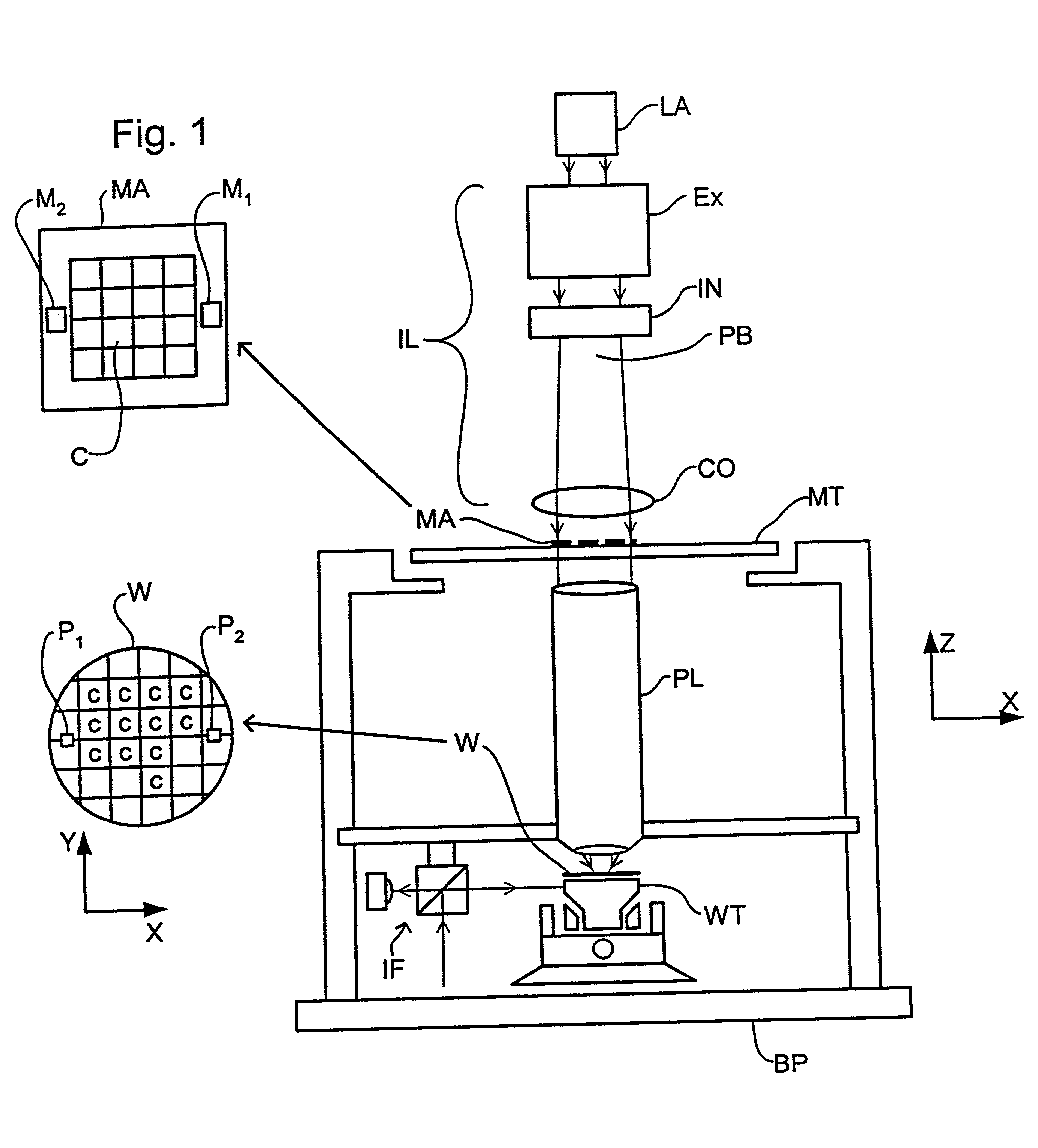
[0106] In this embodiment of the invention, which is the same as the first embodiment except as described below, the interferometric measuring means IF comprises an interferometric displacement measuring device and a second harmonic interferometric device. The second harmonic interferometric device measures the refractivity of the atmosphere in the apparatus at two different wavelengths. In this manner it is possible to determine the effects of pressure and temperature on the refractivity and therefore to adjust accordingly the measurement of the displacement interferometer to account for such variations.

[0107] This is achieved by multiplying the measurement of the second harmonic interferometer by a coefficient K.sub.a and subsequently subtracting this value from the displacement interferometer measurement. Thus, the corrected length, L is given by

L=(DI)-K.sub.a(SHI) (9)

[0108] wherein DI is the displacement interferometer measurement and SHI is the second harmoni...

embodiment 3

[0123] Embodiment 3

[0124] In the third embodiment of the invention, which is the same as the first embodiment except as described below, a second harmonic interferometric device is used to adjust the measurements of the displacement interferometer to account for variations in temperature and pressure. The second harmonic interferometric device is described in Embodiment 2 above. In this third embodiment, the response of the overall interferometric system is adjusted to account for purge gas contamination. This is achieved by off-setting the errors caused by purge gas contamination in each of the two interferometric devices.

[0125] In this embodiment, at least two components make up the purge gas, and the following equation must be substantially fulfilled: 16 m1 (m3 - m2 ) = K a ( 4 )

[0126] wherein .alpha..sub.m1, .alpha..sub.m2 and .alpha..sub.m3 are as defined above; and 17 K a =a1 (a3 - a2 ) ( 5 )

[0127] wherein .alpha..sub.a1, .alpha..sub.a2 and .alpha..sub.a3 are as defined above....

embodiment 4

[0142] Embodiment 4

[0143] According to a further embodiment of the invention, which is the same as the first embodiment except as described below, an apparatus may be used that typically only partially compensates for the effects of temperature, pressure and purge gas contamination. This embodiment may be particularly relevant where the expense or availability of certain components of the preferred purge gas, for example Kr or Xe are prohibitive.

[0144] In this embodiment, the correction coefficient, K, determined by the second harmonic interferometric device may be optimized such that the correction to account for pressure and temperature variation is not quite accurate, but that the errors introduced by the contamination with purge gas are corrected to some extent. Thus, simultaneous correction of pressure, temperature and purge gas errors using an approximate value of the second harmonic interferometer coefficient is used.

[0145] The approximate coefficient may be calculated as des...


PUM

PropertyMeasurementUnit
wavelengthaaaaaaaaaa
interferometric displacement measuringaaaaaaaaaa

Abstract

A lithographic projection apparatus which uses one, and optionally also two or more color interferometric devices to accurately determine the position of a movable table within the apparatus. The apparatus comprises a purge gas source to supply purge gas to a space accommodating at least a part of said movable table, the purge gas being selected such that leakage of the purge gas into the area of operation of the interferometric devices does not cause significant error in the interferometric measurements.

Description

[0001] This application claims priority to U.S. Provisional Patent Application ______ , (M281195) filed Jun. 13, 2001, herein incorporated by reference.[0002] 1. Field of the Invention[0003] The present invention relates generally to lithographic projection apparatus and particularly to lithographic projection apparatus including an interferometer.[0004] 2. Description of the Related Art[0005] The term "patterning structure" should be broadly interpreted as referring to means that can be used to endow an incoming radiation beam with a patterned cross-section, corresponding to a pattern that is to be created in a target portion of the substrate; the term "light valve" has also been used in this context. Generally, the said pattern will correspond to a particular functional layer in a device being created in the target portion, such as an integrated circuit or other device (see below). Examples of such patterning structure include:[0006] A mask table for holding a mask. The concept of...

Claims


Application Information

Patent Timeline
Patent Type & Authority Applications(United States)
IPC IPC(8): C01B23/00G03F7/20
CPCC01B23/00G03F7/70933G03F7/70866G03F7/70775
Inventor PRIL, WOUTER ONNOHENSHAW, PHILIP DENNISVAN DE PASCH, ENGELBERTUS ANTONIUS FRANSISCUSBEEMS, MARCEL HENDRIKUS MARIA
Owner ASML NETHERLANDS BV
Why Eureka
Try Eureka