
Interference suppression in CDMA systems

a communication system and interference suppression technology, applied in the field of interference suppression in cdma communications systems, can solve the problems of insufficient interference treatment, strong interference to the intended signal, and high-rate mobiles manifesting strong interference to the low-rate mobiles, etc., to achieve the effect of improving interference suppression

Active Publication Date: 2002-05-02
INSTITUT NATIONAL DE LA RECHERCHE SCIENTIFIQUE
View PDF3 Cites 388 Cited by
  • Summary
  • Abstract
  • Description
  • Claims
  • Application Information

AI Technical Summary

Benefits of technology

[0028] In a fourth embodiment using a fourth mode conveniently designated ISR-H because it implements null-responses in beamforming using hypothetical realisations of the interference, without any delay, each receiver module of the first group further comprises means for supplying to the spreader possible values of the instant symbols of the output signal and the spreader supplies a corresponding plurality of re-spread signals to each of the receiver modules of the second group. In each receiver module of the second group, the despreader despreads the plurality of re-spread signals and supplies corresponding despread vectors to the beamformer. This embodiment suppresses any sensitivity to data estimation errors and, in most cases, requires a maximum of 3 null constraints per interferer.
[0058] The complexity of the multicode embodiments may be reduced by reducing the number of codes that are used by the despreaders. In particular, the bank of despreaders may use a set of codes that represent summation of the codes of the different NI interferers, to form a compound code which reduces the total number of codes being used in the despreaders.
[0094] FIG. 32 illustrates extension of the frame size to reduce noise enhancement and facilitate asynchronous operation and processing of high data rates;

Problems solved by technology

In CDMA systems, the signals from different users all use the same bandwidth, so each user's signal constitutes noise or interference for the other users.
Power control attempts to maintain the received powers at values that balance the interference observed by the various mobiles, but, in many cases, cannot deal satisfactorily with excessive interference.
Where mobiles with different transmission rates are supported within the same cells, the high-rate mobiles manifest strong interference to the low-rate mobiles.
On the downlink (transmission towards the mobiles) transmissions from base-stations of other cells as well as strong interference from the same base-station to other mobiles may result in strong interference to the intended signal.
Downlink power control may be imprecise or absent altogether.
Power control is presently used to minimize the near-far problem, but with limited success.
Nevertheless, it is expected that future CDMA applications will require even tighter power control with twice the number of updates, yet the near-far problem will not be completely eliminated.
However, none of these detectors is cost-effective to build with significant enough performance advantage over present day systems.
For example, the complexity of the optimal maximum likelihood sequence detector (MLSD) is exponential in the number of interfering signals to be cancelled, which makes its implementation excessively complex.
A disadvantage of such decorrelators is that they cause noise enhancement.
In both cases, the processing burden still appears to present implementation difficulties.
Both SIC detectors and PIC detectors require multi-stage processing and the interference cancellation achieved is limited by the amount of delay or complexity tolerated.
These detectors are also very sensitive to channel, power and data estimation errors.
A disadvantage of this approach is its sensitivity to the data and power estimates, i.e., their accuracy and the sign of the data.
A wrong decision will result in the interference component being added rather than subtracted, which will have totally the wrong effect.
In practice, however, there will be significant differences between the power levels at which the different users signals are received at the base station antenna.
Also, imperfect power control will result in power differences, i.e., channel variations may result in received powers different from their intended values, despite the best effort of the power-control process to equalize them.

Method used


Image

  • Interference suppression in CDMA systems
  • Interference suppression in CDMA systems
  • Interference suppression in CDMA systems

Examples


Embodiment Construction

[0112] In the following description, identical or similar items in the different Figures have the same reference numerals, in some cases with a suffix.

[0113] The description refers to several published articles. For convenience, the articles are cited in full in a numbered list at the end of the description and cited by that number in the description itself. The contents of these articles are incorporated herein by reference and the reader is directed to them for reference.

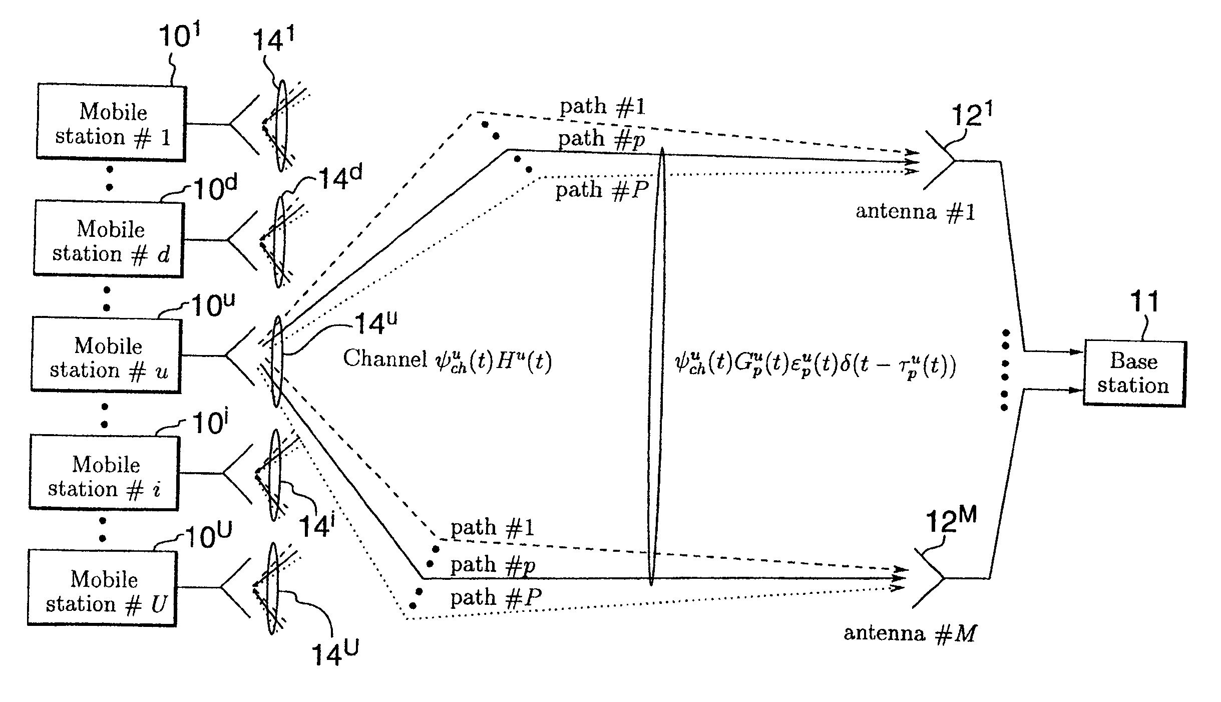
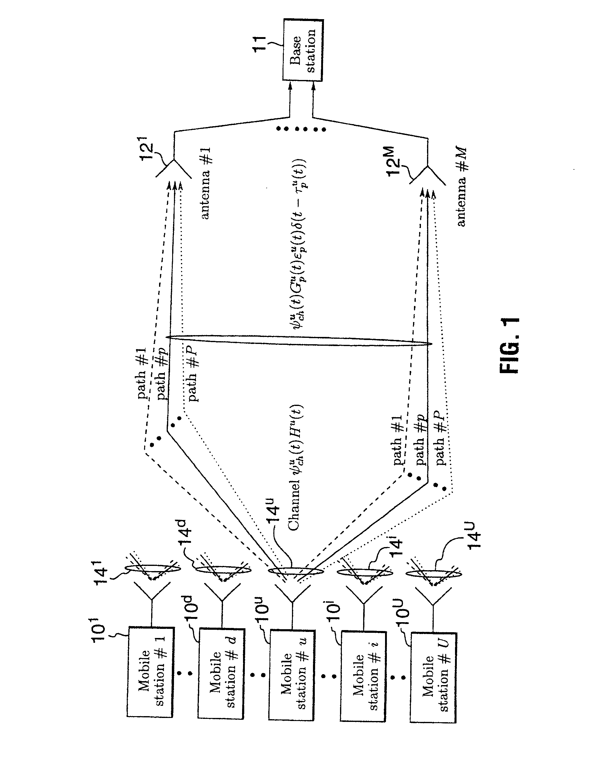
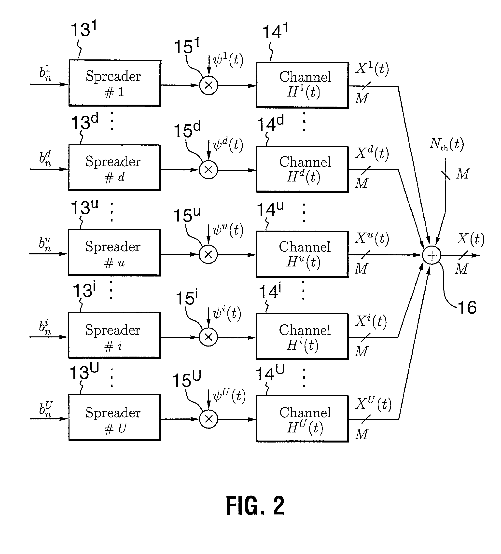
[0114] FIGS. 1 and 2 illustrate the uplink of a typical asynchronous cellular CDMA system wherein a plurality of mobile stations 10.sup.1 . . . 10.sup.U communicate with a base-station 11 equipped with a receiving antenna comprising an array of several antenna elements 12.sup.1 . . . 12.sup.M. For clarity of depiction, and to facilitate the following detailed description, FIGS. 1 and 2 illustrate only five of a large number (U) of mobile stations and corresponding propagation channels of the typical CDMA system, o...


PUM


Abstract

A receiver of the present invention addresses the need for improved interference suppression without the number of transmissions by the power control system being increased, and, to this end, provides a receiver for a CDMA communications system which employs interference subspace rejection to tune a substantially null response to interference components from selected signals of other user stations. Preferably, the receiver also tunes a substantially unity response for a propagation channel via which a corresponding user's signal was received. The receiver may be used in a base station or in a user / mobile station.

Description

DESCRIPTION[0001] 1. Technical Field[0002] The invention relates to Code-Division Multiple Access (CDMA) communications systems, which may be terrestrial or satellite systems, and in particular to interference suppression in CDMA communications systems.[0003] 2. Background Art[0004] Code-Division Multiple Access communications systems are well known. For a general discussion of such systems, the reader is directed to a paper entitled "Multiuser Detection for CDMA Systems" by Duel-Hallen, Holtzman and Zvonar, IEEE Personal Communications, pp. 46-58, April 1995.[0005] In CDMA systems, the signals from different users all use the same bandwidth, so each user's signal constitutes noise or interference for the other users. On the uplink (transmissions from the mobiles) the interference is mainly that from other transmitting mobiles. Power control attempts to maintain the received powers at values that balance the interference observed by the various mobiles, but, in many cases, cannot de...

Claims


Application Information

Patent Timeline
Patent Type & Authority Applications(United States)
IPC IPC(8): H04B1/707H04B1/7105H04B7/08
CPCH04B7/086H04B1/71052
Inventor AFFES, SOFIENEHANSEN, HENRIKMERMELSTEIN, PAUL
Owner INSTITUT NATIONAL DE LA RECHERCHE SCIENTIFIQUE
Learn More