Light guide plate, surface light source device and display

a surface light source and light guide technology, applied in waveguides, lighting and heating apparatuses, instruments, etc., can solve the problems of inefficient direction conversion, unsatisfactory brightness, and very irrational orientation of micro-reflectors, and achieve bright display and high efficiency

Inactive Publication Date: 2002-05-09
ENPLAS CORP
View PDF0 Cites 40 Cited by
  • Summary
  • Abstract
  • Description
  • Claims
  • Application Information

AI Technical Summary

Benefits of technology

0017] An object of the present invention is to provide at light guide plate suitable for introducing light from a plurality of input portions using point-like light sources, a surface light source device and a display employing the light guide plate. Vie

Problems solved by technology

As known well, a simply transparent light guide plate without any modification is capable of deflecting light little, providing a unsatisfactory brightness.
However, a problem arises if the above-proposed prior art is applied to a case where a plurality of point-like light sources are adopte

Method used


Image

  • Light guide plate, surface light source device and display
  • Light guide plate, surface light source device and display
  • Light guide plate, surface light source device and display

Examples


first embodiment

[0044] (1) First Embodiment

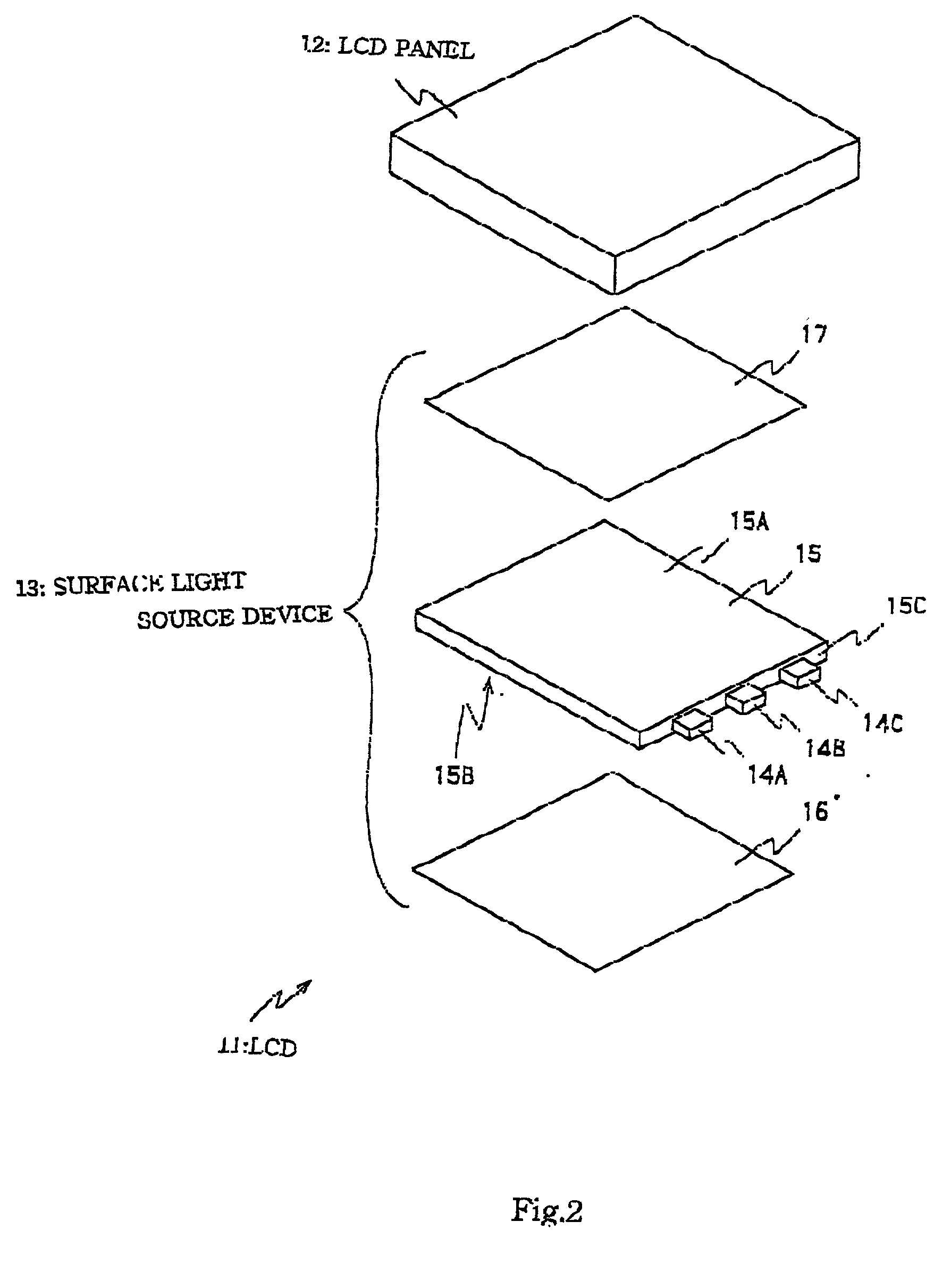
[0045] FIG. 2 is an exploded perspective view of the liquid crystal display of the first embodiment. A liquid crystal display 11 which is applied, for example, to a portable telephone, has a liquid crystal display panel 12 illuminated by a back-lighting surface light source device 18. The light source device 18 has a light guide plate 15. The light guide plate 15 is provided input portions at three locations along one end face and light emitting diodes as point-like light sources 14A, 14B and 14C are disposed at each of the input portions.

[0046] The light guide plate 15 have major faces one of which provides an emission face 15D along which a light diffusion sheet 17 is disposed. A reflection sheet 16 is disposed along a back face 15B opposite with emission face 15A. The reflection sheet 17 is made of a white sheet member, reflecting and returning a leaking light once escaping through the back face 15B into the light guide plate 15, thereby avoiding loss o...

second embodiment

[0075] (2) Second Embodiment

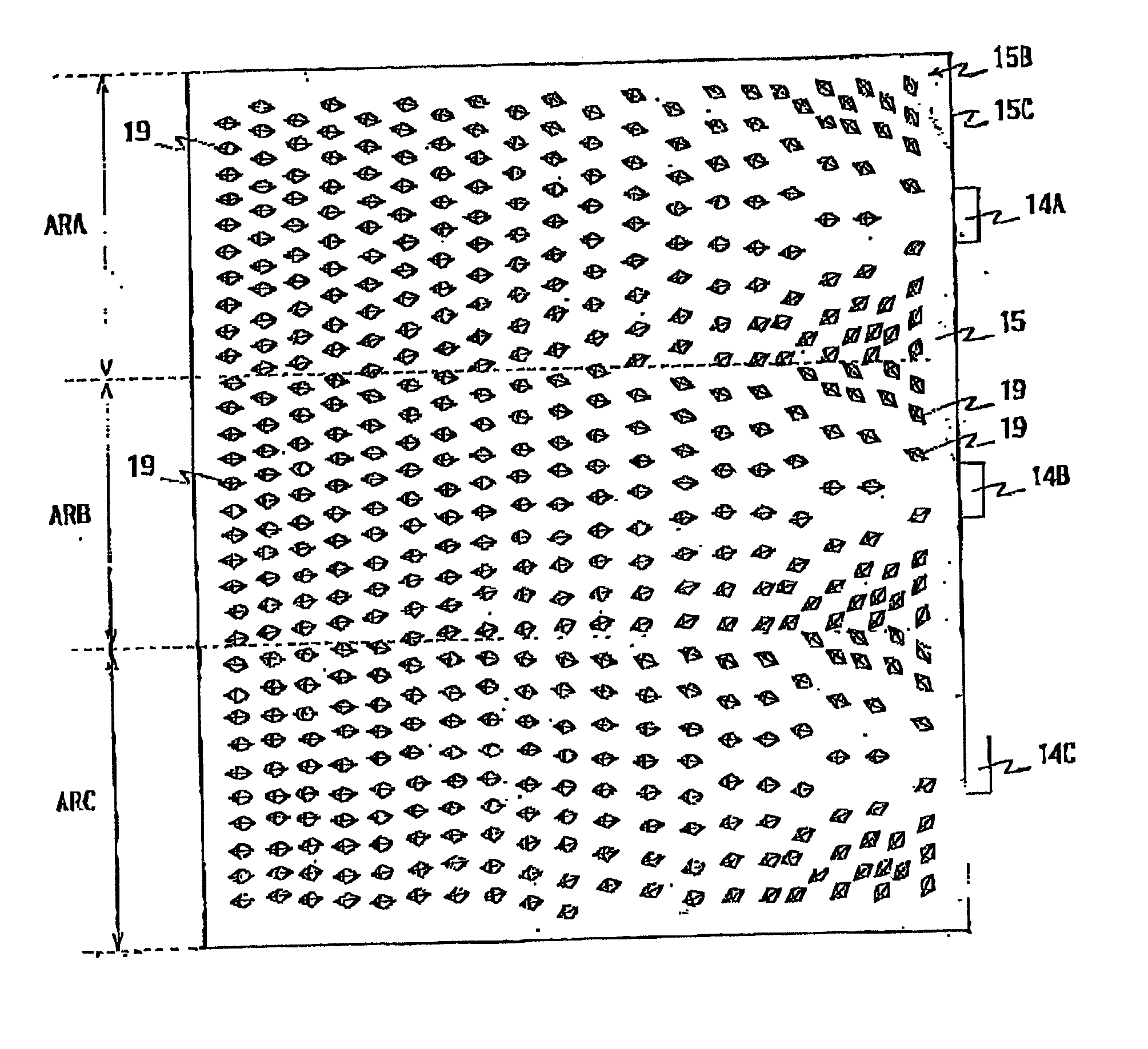
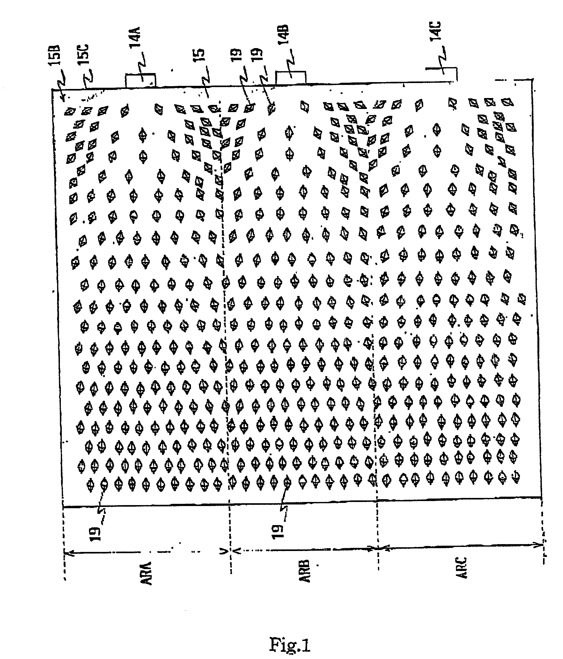
[0076] FIG. 4 is a plan view illustrating, in the same manner as FIG. 1, a back face of light guide plate employed in a surface light source device applied to a liquid crystal display of the second embodiment in accordance with the present invention. This embodiment is not different from the first embodiment in structure an function except that a light guide plate 25 is employed instead of the light guide plate 15 (FIG. 1). Accordingly longwinded and repeated description is omitted.

[0077] The light guide plate 25 has a back face 25B that is featured by an micro-reflector arrangement different from that of the back face 15B of the light guide plate 16. Except this, the light guide plates 15 and 25 are not different. Accordingly, the following description is generally focused on the micro-reflector arrangement of the back face 25.

[0078] The second embodiment is an embodiment such that the first embodiment (light guide plate 15) is further improved. That is,...


PUM


Abstract

A surface light source device and display utilize a light guide plate provided with micro-reflectors arranged in an orientation suitable for a plurality of input portions having point-like light emitters, respectively. A light guide plate 15 has a back face divided into areas ARA to ARC to each of which each input portion having each of LEDs 14A to 14C is shared. Micro-reflectors 19 in each of areas ARA to ARC are orientated as to be directed to each of LEDs 14A to 14C correspondingly, effecting an effective direction conversion. Emitted light is incident to a liquid crystal display panel generally at a right angle via a light diffusion sheet. Some micro-reflectors 19 in each of areas ARA to ARC may be arranged as to be directed to an adjacent input portion. Micro-reflectors may be shaped like quadrangle pyramid projections, cylindrical dents or V-shaped dents.

Description

[0001] 1. Field of Invention[0002] The present invention relates to a light guide plate emitting light from an emission face after applying direction-conversion within the light guide plate to light supplied thereto sideways, and to a surface light source device and display employing the light guide plate.[0003] 2. Related Art[0004] A well-known technique gives a surface light source device that employs a light guide plate having a side part for light introduction and an emission face provided by one of two major faces (i.e. faces larger than end faces), the surface light source device being applied to various uses such as back-lighting for a liquid crystal display. A surface light source device of such a type has a basic performance greatly depending on a light guide plate employed therein.[0005] A basic function of a light guide plate is to change a propagation direction (roughly in parallel with an emission face of the light guide plate) of light introduced into the light guide p...

Claims


Application Information

Patent Timeline
IPC IPC(8): F21V8/00G02B6/00F21Y101/02G02B6/42G02F1/1335G02F1/13357
CPCG02B6/0018G02B6/0021Y10S385/901G02B6/0061G02B6/0068G02B6/0036G02F1/1335
Inventor OHKAWA, SHINGO
Owner ENPLAS CORP
Why Eureka
Try Eureka