Optical device for eliminating stray light

a technology of optical devices and stray light, applied in the field of conventional optical systems, can solve the problems of affecting the contrast ratio of the optical system, and the amount of luminance output of the optical system, and achieve the effect of reducing the amount of luminance outpu

Inactive Publication Date: 2002-05-16
CORETRONIC
View PDF0 Cites 6 Cited by
  • Summary
  • Abstract
  • Description
  • Claims
  • Application Information

AI Technical Summary

Benefits of technology

[0006] In order to achieve the object mentioned above, an optical device for eliminating the stray light ("stray light" is the common name for above mentioned chromatic halo 60) is provided according to the invention. The optical device is provided at a stop 20 of a illuminating system in an optical system of the "digital light processing" (DLP) that consists of the stop 20 of the illuminating system, a DMD 30, a stop 40 of a projection lens, and a screen 50. And, the stray light is the chromatic halo 60 at the peripheral area on the screen. Wherein, the optical device includes a reflecting mirror designed of an adjustable angle and installed at the area B near the periphery of the stop of the illuminating system. And, the chromatic halo generated by the light beam at the area B near the periphery of the stop of the illuminating system is reflected from the DMD and is transmitted into the stop of the projection lens, and then is projected on the screen 50. And, the reflecting mirror is used to reflect the light beam at the area B near the periphery of the stop of the illuminating system so as to divert the original transmitting path of the light beam. Thus, the light beam at area B is reflected from the DMD and is uniformly transmitted into the stop of the projection lens. Thereby, the contrast ratio of the optical system is increased, and the quality of the output image is improved, and the efficiency of the DLP system is enhanced, and the luminance projected on the screen 50 is improved.

Problems solved by technology

Especially when a black image is projected, since the existence of the chromatic halo results in an imperfect black image, the contrast ratio of the optical system is therefore affected.
Therefore, if the light beam at this area is completely covered, the amount of lumina output by the optical system is greatly affected.

Method used


Image

  • Optical device for eliminating stray light
  • Optical device for eliminating stray light
  • Optical device for eliminating stray light

Examples


Embodiment Construction

[0015] The aspects of embodiments of an optical device for eliminating the stray light according to the invention are illustrated with reference of the accompanying drawings as follow.

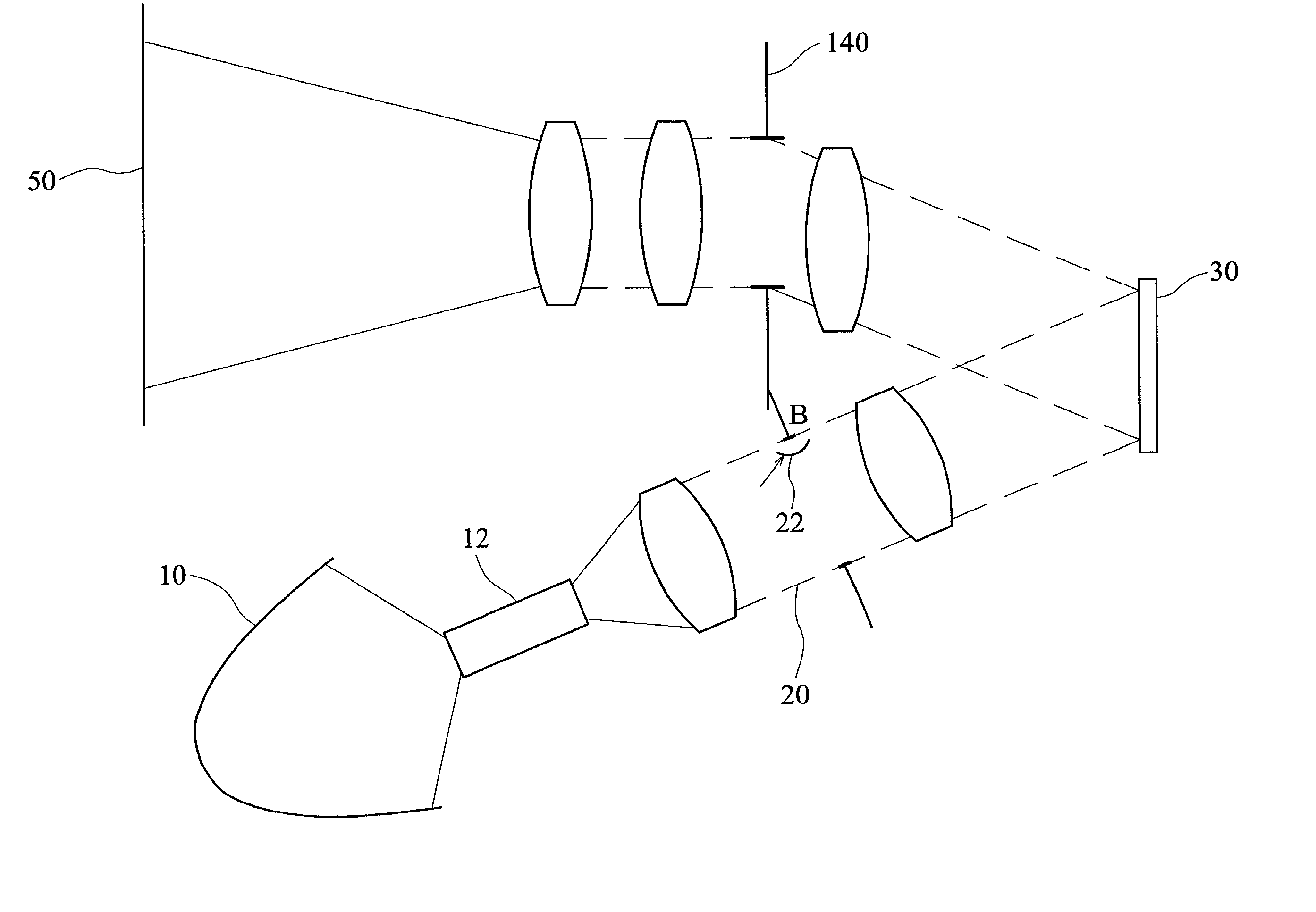
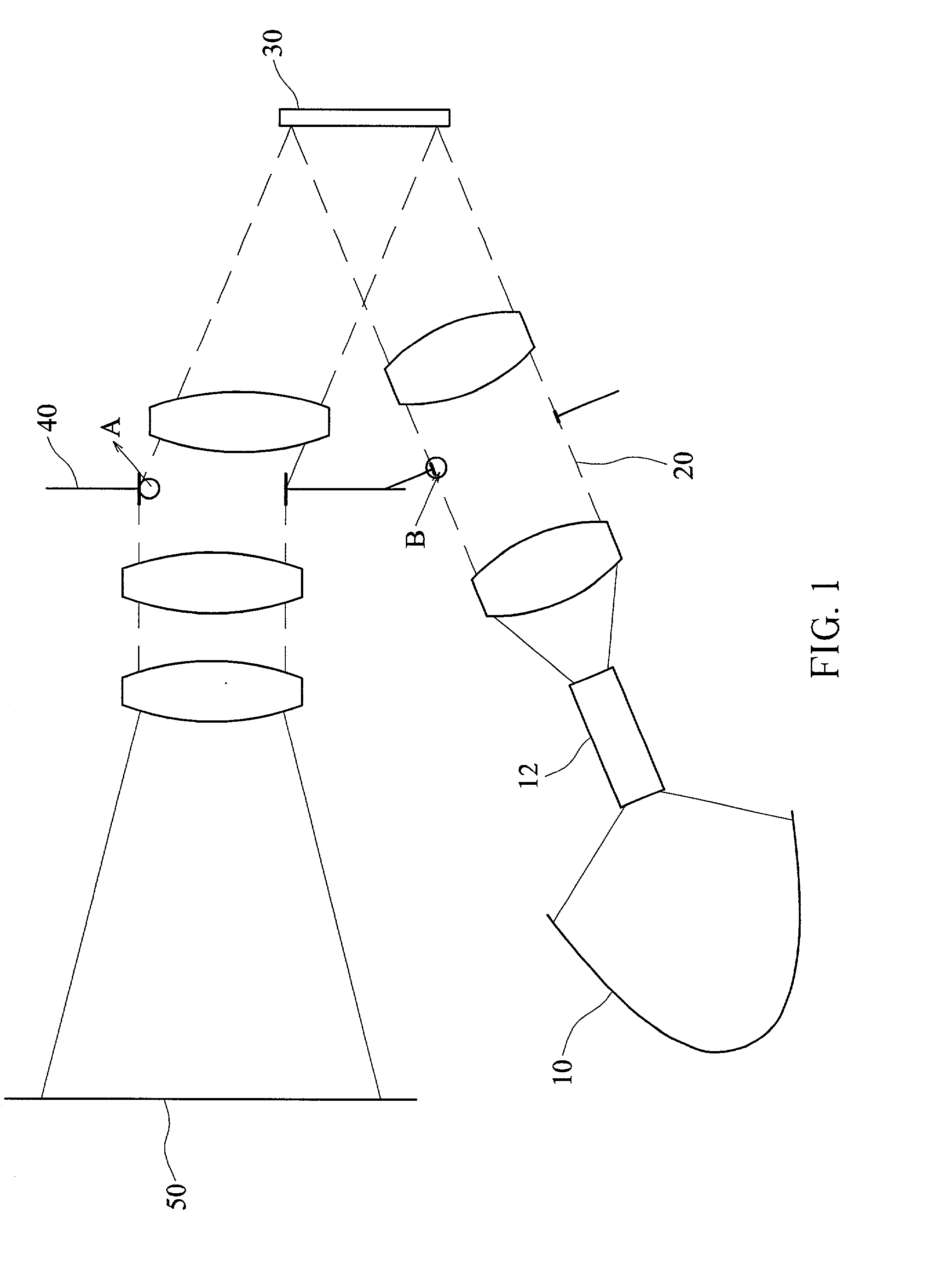
[0016] FIG. 3 is a schematic diagram for a small-sized reflecting mirror (with a flat surface or a curved surface) installed near the periphery a stop of an illuminating system according to the invention. As shown in FIG. 3, the optical system according to the invention employs a "digital micromirror device" (DMD) or a "reflecting type liquid crystal on silicon" (LCOS). And, the optical system consists of a light source 10, an integration rod 12, a stop 20 of an illuminating system, a reflecting panel (DMD or LCOS) 30, a stop 140 of a projection lens with an aperture angle greater than 10 degree, and a screen 50 for display. The optical device for eliminating the stray light according to the invention is a reflecting mirror 22 installed at the stop 20 of the illuminating system while the stray light is...


PUM


Abstract

An optical device for eliminating the stray light is provided at a stop of an illuminating system in an optical system of "digital light processing" (DLP). The optical system consists of a stop of an illuminating system, a "digital micromirror device" (DMD), a stop of a projection lens, and a screen while the stray light is a chromatic halo at the peripheral area on the screen. Wherein, the optical device includes a reflecting mirror designed of an adjustable angle and installed near periphery of the stop of the illuminating system. The chromatic halo is generated from the light beam at the periphery area. And, the light beam is reflected from the DMD and is transmitted into the stop of the projection lens, and then is projected on the screen. And, the reflecting mirror is used to reflect the light beam at the periphery area so as to divert the original transmitting path of the light beam such that the light beam is reflected from the DMD and is uniformly transmitted into the stop of the projection lens. Thus, the contrast ratio of the illuminating system is increased, and the quality of the output image is improved, and the efficiency of the DLP system is enhanced, and the luminance projected on the screen is improved.

Description

[0001] The invention relates to an optical device for eliminating the stray light, and particularly to an optical device diverting the original transmitting path of the stray light beam to improve the quality of the output image and the luminance projected on a screen.DESCRIPTION OF THE RELATED ART[0002] FIG. 1 is a schematic diagram of an conventional optical system employing a "digital micromirror device" (DMD) or a "reflecting type liquid crystal on silicon" (LCOS). FIG. 2 is an enlarged schematic diagram of a conventional chromatic halo generated by a stop of a projection lens with an aperture angle greater than 10 degree in coordination with the DMD chip with 10 degree turning angle. As shown in FIG. 1 and FIG. 2, the conventional optical system, using the DMD chip or the LCOS consists of a light source 10, a integration rod 12, a stop 20 of an illuminating system, a reflecting panel (DMD or LCOS) 30, a stop 40 of a projection lens, and a screen 50 for display.[0003] By means o...

Claims


Application Information

Patent Timeline
Patent Type & Authority Applications(United States)
IPC IPC(8): G02B5/00G02B3/00G02B5/04G02B5/08G02B5/10G02B26/08G02B27/18G03B21/00H04N5/74
CPCH04N5/7458G02B26/0841
Inventor CHENG, CHUAN-TE
Owner CORETRONIC
Why Eureka
Try Eureka