Eureka AIR delivers breakthrough ideas for toughest innovation challenges, trusted by R&D personnel around the world.

Network diagnostic meter

a network diagnostic and meter technology, applied in the field of industrial communication networks, can solve the problems of inconvenient use of specialized people of such a high skill level, difficult to diagnose the various types of devices which may be employed, and the complexity of the network of modern industrial automation systems

Inactive Publication Date: 2002-05-16
WOODHEAD IND INC
View PDF0 Cites 10 Cited by
  • Summary
  • Abstract
  • Description
  • Claims
  • Application Information

AI Technical Summary

Benefits of technology

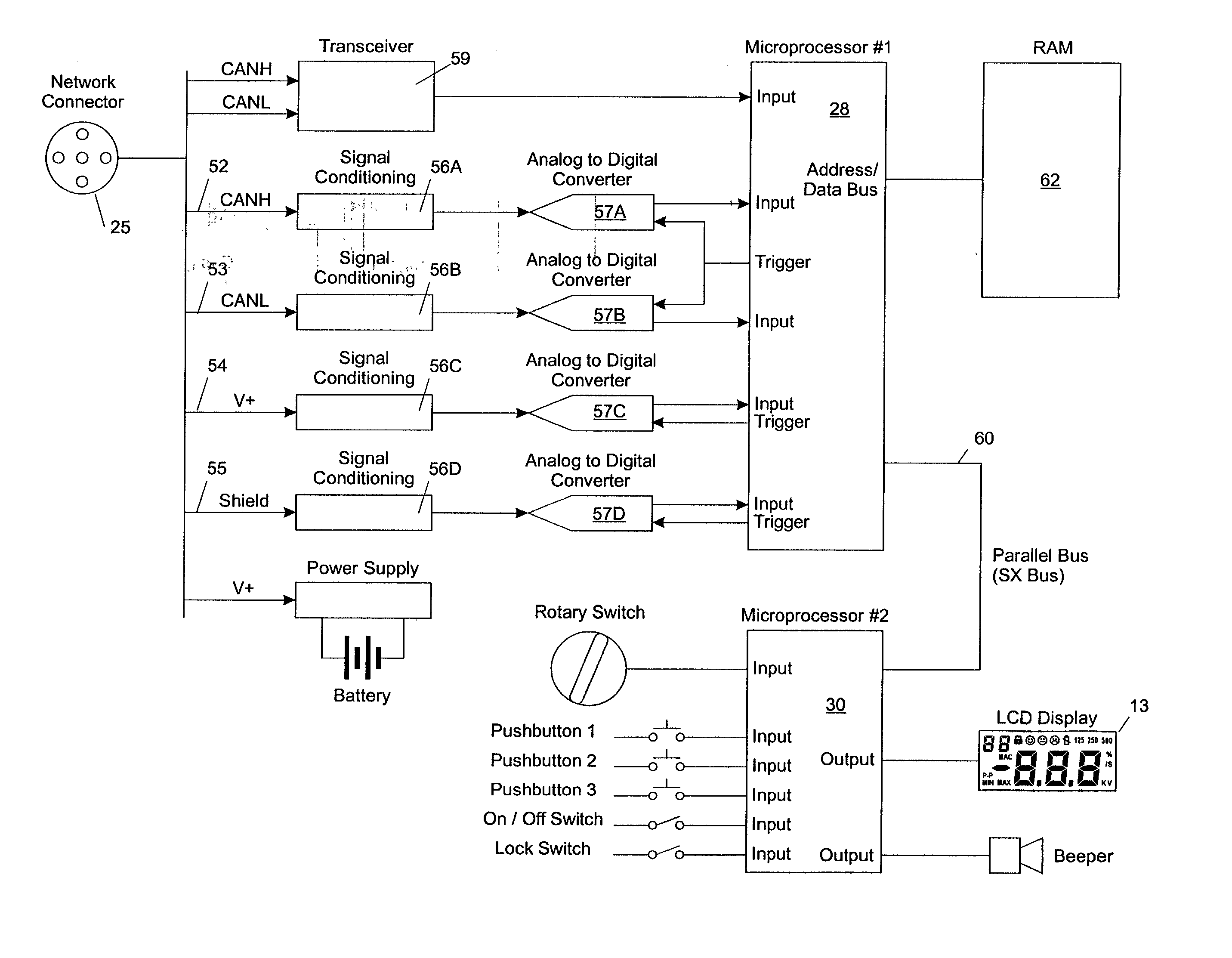
0009] A display (liquid crystal display, or LCD in the illustrated embodiment) is included. The display is operated by an interface data processor coupled to the main data processor (simply "processor") by means of a bus. Additional memory is provided for the main processor.
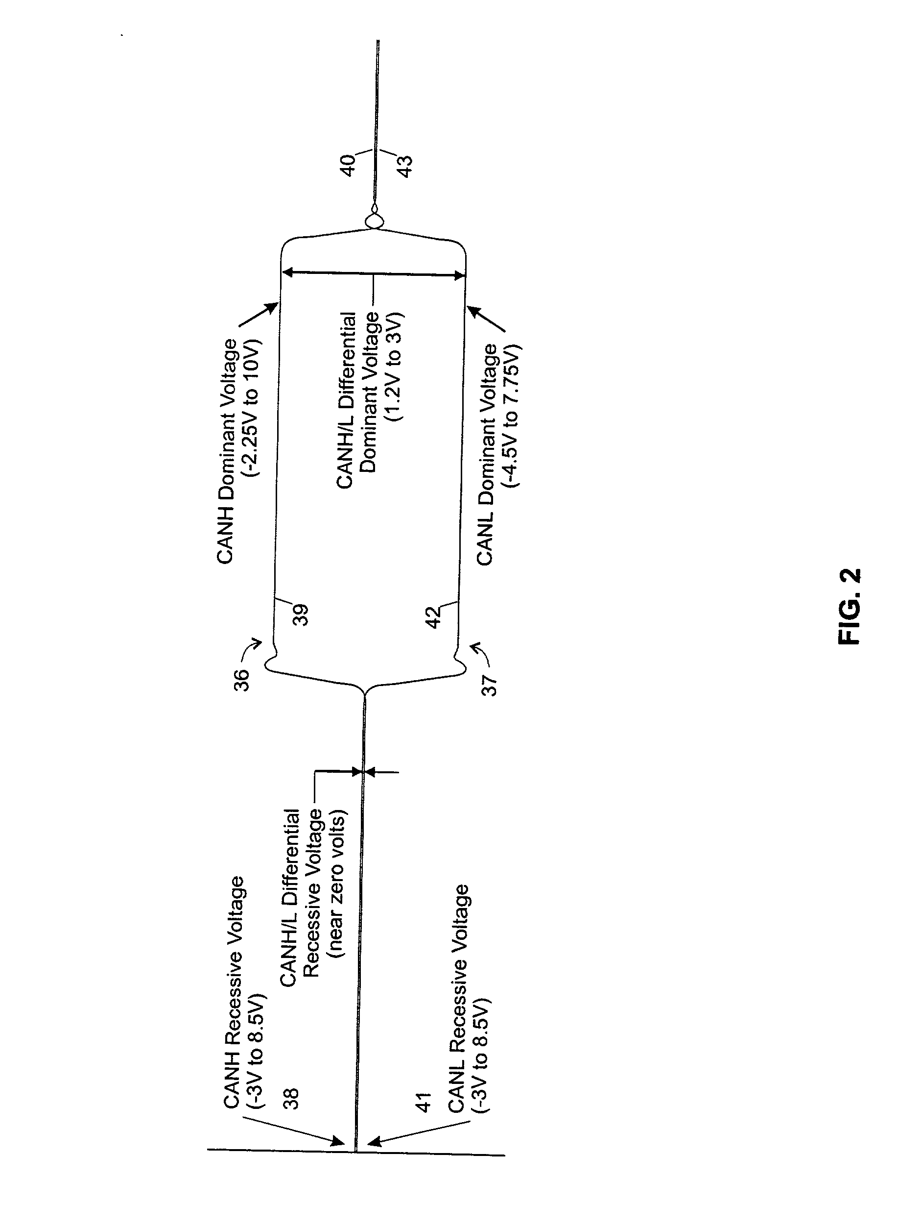
0010] As used herein, a "network" includes a series of devices, such as computers, programmable logic controllers, displays, sensors, control elements or the like, commonly used in industrial automation systems. A "node" is any such device connected to the network, including, for example, the test device of the present invention. According to DeviceNet protocol (an industrial communication protocol standard based on the CAN or Controller Area Network, protocol standard), there are two data signal lines, one designated as the CAN High or "CANH" line and the other is designated CAN Low or "CANL", according to convention. The system of the present invention employs a main processor receiving the incoming data signals and sampling those signals for an accurate determination of amplitude which is then converted to a corresponding digital signal representation and stored in memory to establish a database of

Problems solved by technology

Such tools are of limited use in the complex networks of modern industrial automation systems.
Networks of this type, considering the physical connections, the nature of the various types of devices which may be employed, including PLCs and personal computers and display devices, as well as the signal protocols, can be very difficult to diagnose when a problem arises.
Yet, it is not economical to have a specialized person of such a high skill level simply waiting until a fault occurs because, despite the occurrence of occasional faults, the systems are quite reliable.

Method used


Image

  • Network diagnostic meter
  • Network diagnostic meter
  • Network diagnostic meter

Examples


Embodiment Construction

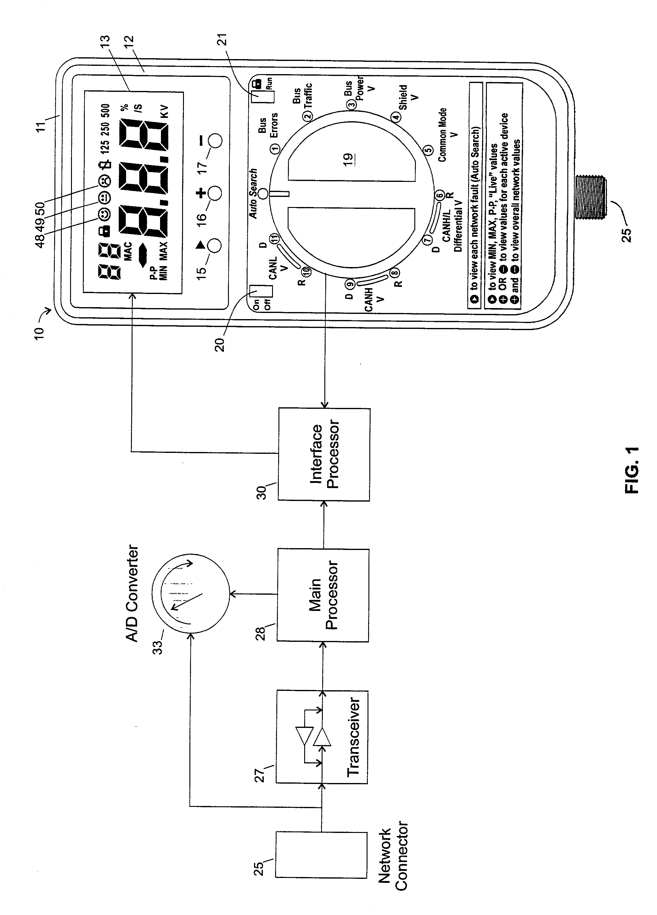
[0025] Turning first to FIG. 1, reference numeral 10 generally designates a diagnostic meter for a communication network of the type used in industrial automation applications. The meter 10 includes a casing 11, preferably made of rubber or other moldable protective, elastomeric material for both buffering any force due to a fall, in the event the instrument is dropped, and for providing protection against water, oils and other liquids. On the face 12 of the housing 11, there is a display 13. Beneath display 13 are three push buttons for actuating associated switches. These are referred to respectively as the "Advancing" or incrementing switch 15, the "Plus" switch 16 and the "Minus" switch 17, and they will be further described below. Beneath the display 13 and the switches 15-17 is a rotary switch 19 which is itself of conventional design and has twelve individual stations, designated respectively 1-11 and "Auto Search" at the twelve o'clock (top) position. Although a rotary switc...


PUM


Abstract

A portable test meter is disclosed for measuring, calculating, recording and monitoring significant system parameters for a local communication network of the type used in industrial automation applications. The meter is disclosed in the context of a network employing the DeviceNet protocol. For each network parameter of interest, a rotary switch selects a desired one for display. An auto search mode selectable by the operator, increments through selected network parameters and compares measured or calculated values against stored data representing acceptable, marginal, or unacceptable conditions, and an associated visual indicia is displayed for each unacceptable or margin condition detected.

Description

RELATED APPLICATION[0001] This application is a non-provisional application claiming the benefit of the filing date of copending U.S. Provisional Applications No. 60 / 248,046 filed Nov. 13, 2000 and No. 60 / 287,528 filed Apr. 30, 2001.FIELD OF THE INVENTION[0002] The present invention relates to industrial communication networks; and more particularly, it relates to a diagnostic test system for performing a wide range of diagnostic tests in situ on an industrial communication network using a hand-held meter of convenience size.BACKGROUND OF THE INVENTION[0003] Industrial automation installations have used programmable logic controllers (PLCs) in combination with a variety of individual devices, such as presses, robots, visual displays, solenoid actuators and many others, for achieving efficient information communication and control in manufacturing environments. A communication network employing its own protocol and signal specifications is typically used to interface all of the vario...

Claims


Application Information

Patent Timeline
IPC IPC(8): G01R31/319
CPCG01R31/31914
Inventor JONES, NICOLAS D. L.MONTGOMERY, STEVEN R.GRAHAM, ROBERT
Owner WOODHEAD IND INC
Why Eureka
Eureka Blog
Learn More