Fuel injector with an optimized metering device

a fuel injector and metering device technology, which is applied in the direction of turbine/propulsion fuel valves, mechanical equipment, machines/engines, etc., can solve the problems of non-uniform flow rate between injectors, harmful to the proper operation of turbomachines, and the prior art still suffers from a major drawback, so as to reduce the non-uniform flow rate and save time

Inactive Publication Date: 2002-05-23
HISPANO SUIZA SA
View PDF0 Cites 15 Cited by
  • Summary
  • Abstract
  • Description
  • Claims
  • Application Information

AI Technical Summary

Benefits of technology

[0005] An object of the present invention is thus to provide a fuel injector which makes it possible to reduce flow rate non-uniformity between the various injectors in a common combustion chamber to a considerable extent. Another object of the invention is to provide a device which makes it possible for the adjustment of fuel injection flow rates into the combustion chamber to be made simpler and more reliable for each of the injectors. Another object of the invention is to provide a device which also makes it possible to save time when individually adjusting these flow rates. A further object of the injector is to provide a device that is capable of overcoming friction in the metering valve of such an injector.
[0007] With this particular structure, and at high flow rates (above the second determined pressure S2), any dispersion in the flow rate characteristics of the utilization means is avoided and adjustment of the maximum flow rate at which fuel can be injected is made considerably simpler.

Problems solved by technology

That prior art nevertheless suffers from a major drawback.
This results in great non-uniformity of flow rate between injectors which is particularly harmful to proper operation of the turbomachine.

Method used


Image

  • Fuel injector with an optimized metering device
  • Fuel injector with an optimized metering device
  • Fuel injector with an optimized metering device

Examples


Embodiment Construction

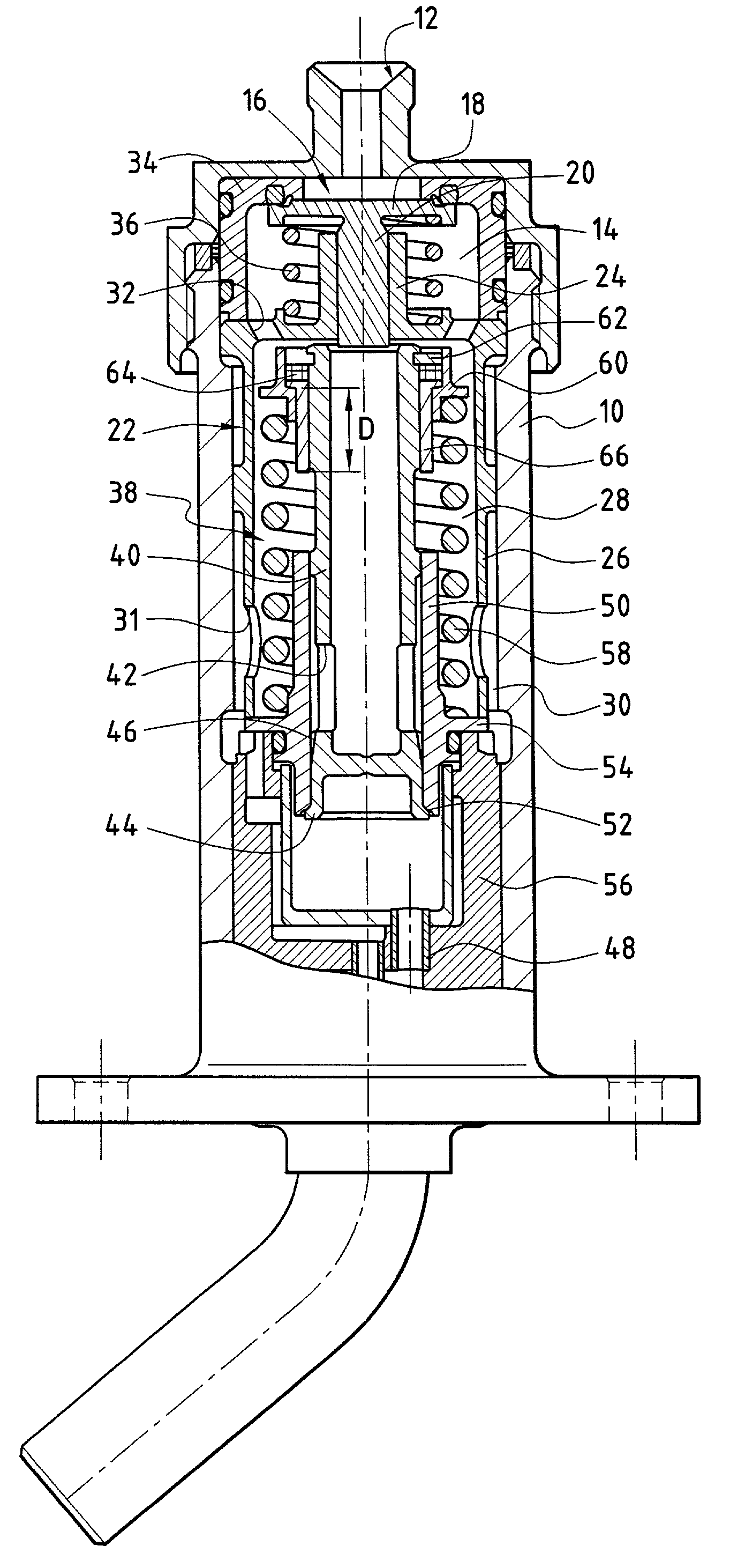
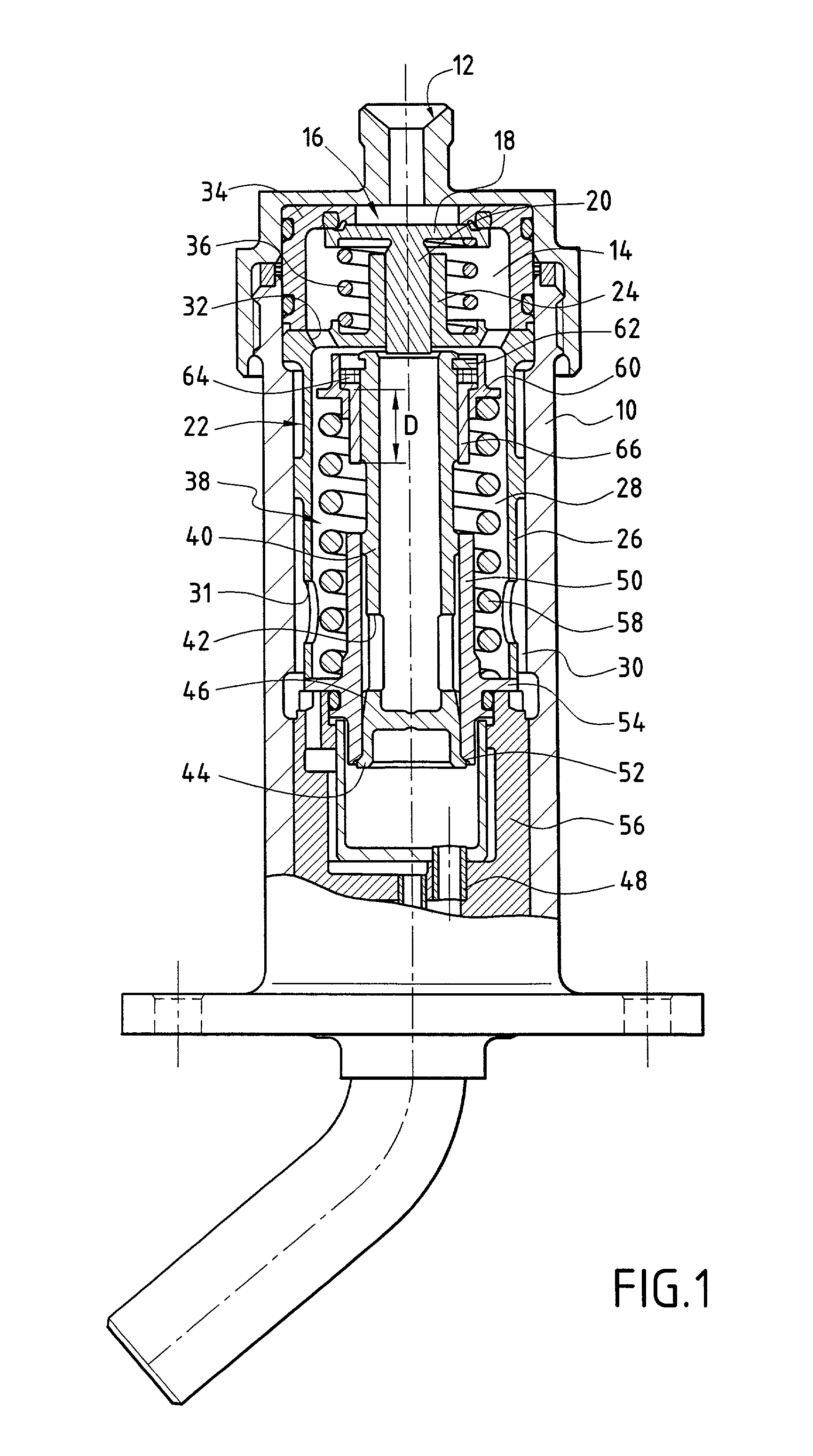
[0014] FIG. 1 shows a fuel injector for a turbomachine combustion chamber. This injector can be a so-called "pilot" injector for use in starting, in which case the injector is in operation all the time that the engine is running, or it can be a "main" injector for use during cruising, in which case it can either be in operation or extinguished while the engine is running. The injector comprises an injector body 10, a fuel admission orifice 12 for receiving the fuel under pressure from a suitable fuel pump (not shown) and opening out into an inlet chamber 14 for fuel flow inside this injector body. A shut-off valve 16 for sealing the injector when not in operation and conventionally constituted by a valve head 18 and a valve stem 20 is mounted in said fuel inlet chamber and is held in position by means of a sleeve 22 whose central tubular portion 24 forms a valve support and which further includes a peripheral cylindrical portion 26 which extends downstream from said central portion ...


PUM


Abstract

A fuel injector has a metering valve arranged to open under a predetermined feed pressure which constitutes a first threshold pressure, and to remain open in response to said feed pressure increasing so as to deliver fuel to fuel utilization means. The flow rate of fuel passing through the injector is metered to feed said utilization means so long as the feed pressure remains below a second threshold pressure greater than the first threshold pressure. Above the second threshold pressure, the metering valve behaves like a fixed diaphragm as a function of the fluid flow sections formed therethrough. Individual adjustment means are provided so as to enable said second threshold pressure to be adjusted for each injector to ensure that fuel is injected at a uniform flow rate by all of the injectors in a combustion chamber.

Description

[0001] The present relates to the general field of devices for adjusting a fluid flow, and it relates more particularly to fuel injectors in a turbomachine combustion chamber.PRIOR ART[0002] The rate at which fuel is fed into a turbojet or a turboprop (referred to below as a "turbomachine") is adjusted by means of injectors which are designed to deliver a first flow of "main" fuel while the turbomachine is in a starting stage and when operating at low power ("idling"), and a second flow of "secondary" fuel during subsequent stages of operation all the way to full power.[0003] French patent application No. FR 2 540 186 illustrates a typical example of a fuel injector for a turbomachine that comprises firstly a stop valve whose spring is adjusted in such a manner as to open at a predetermined fuel feed pressure corresponding to the starting stage and to remain open above said predetermined pressure, and secondly a metering valve whose spring is adjusted to open at a feed pressure that...

Claims


Application Information

Patent Timeline
Patent Type & Authority Applications(United States)
IPC IPC(8): F02C7/232F02C9/26
CPCF02C9/263F02C7/232
Inventor LAVIE, ALAINMARTELLI, STEPHANIEMICHAU, MARIONRODRIGUES, JOSETIEPEL, ALAIN
Owner HISPANO SUIZA SA
Why Eureka
Try Eureka