Binding device for a big baler

a technology for binding devices and balers, which is applied in the field of binding devices for balers, can solve the problems of high "loosening" of twine, loss of a portion of the compressed density of bales, and damage to twine needles

Inactive Publication Date: 2002-06-06
LELY VERMEER MASCHFAB
View PDF0 Cites 2 Cited by
  • Summary
  • Abstract
  • Description
  • Claims
  • Application Information

AI Technical Summary

Problems solved by technology

This, however, results in a rather high "loosening" of the twine with a loss of a portion of the compressed density of the bale.
In addition, the twine needles can become damaged during a following compression, as the needle partially remains in the baling channel when a next compression cycle starts.
In addition to a complex and prone to failure design of the kinematic mechanism, the disclosed binding device has two other big drawbacks.
Because of the foregoing drawbacks, the solution according to DE 10 95 044 did not find a practical application.
Despite numerous attempts (see, e.g., DE 10 69 419) to find a solution of the above-discussed problem, no solution, which could have a practical application, was found.
However, the further away from the dead point the binding starts, the greater would be the twine loosening and the loss of the compressed density of the formed bale.

Method used


Image

  • Binding device for a big baler
  • Binding device for a big baler
  • Binding device for a big baler

Examples


Embodiment Construction

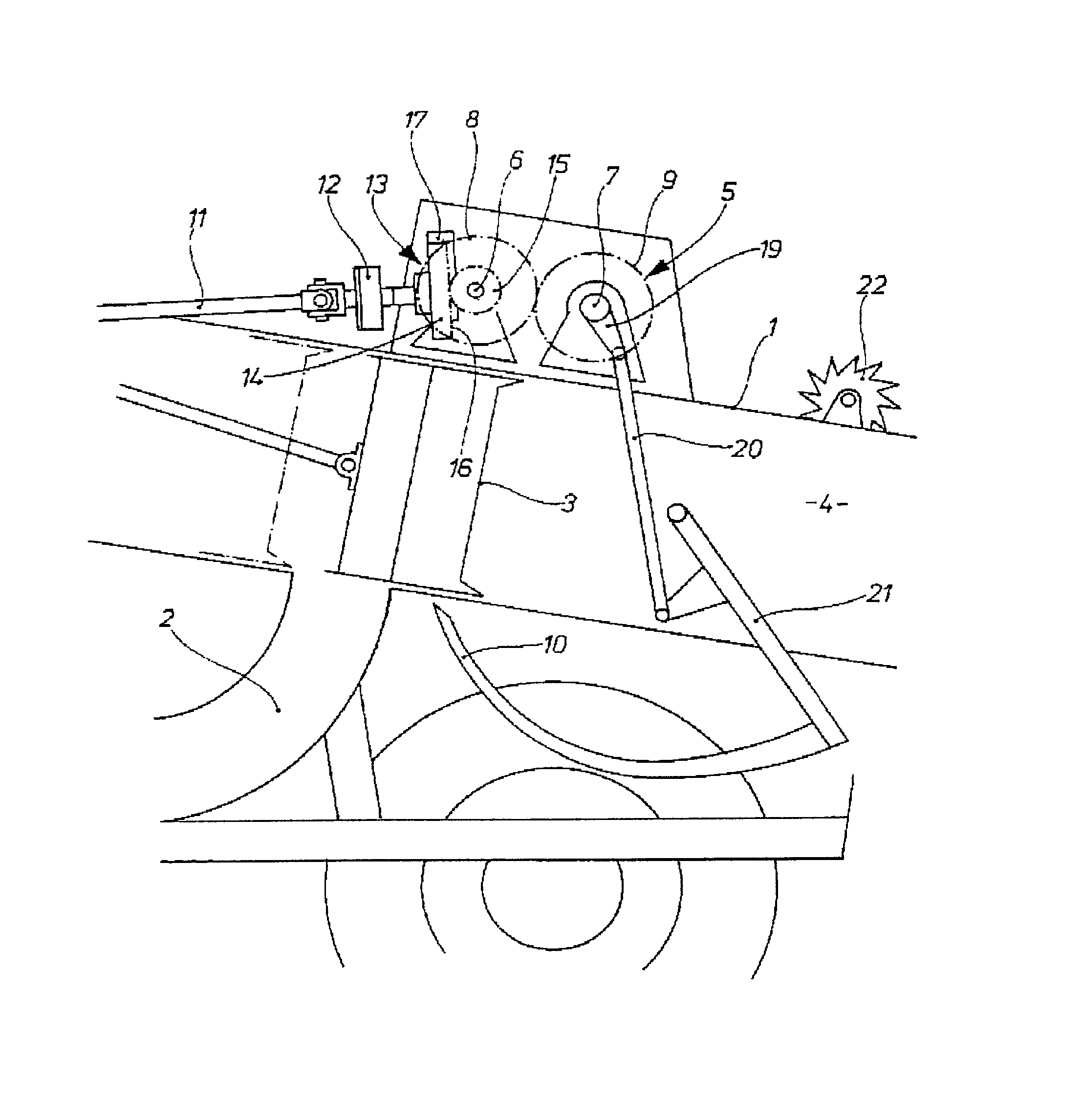
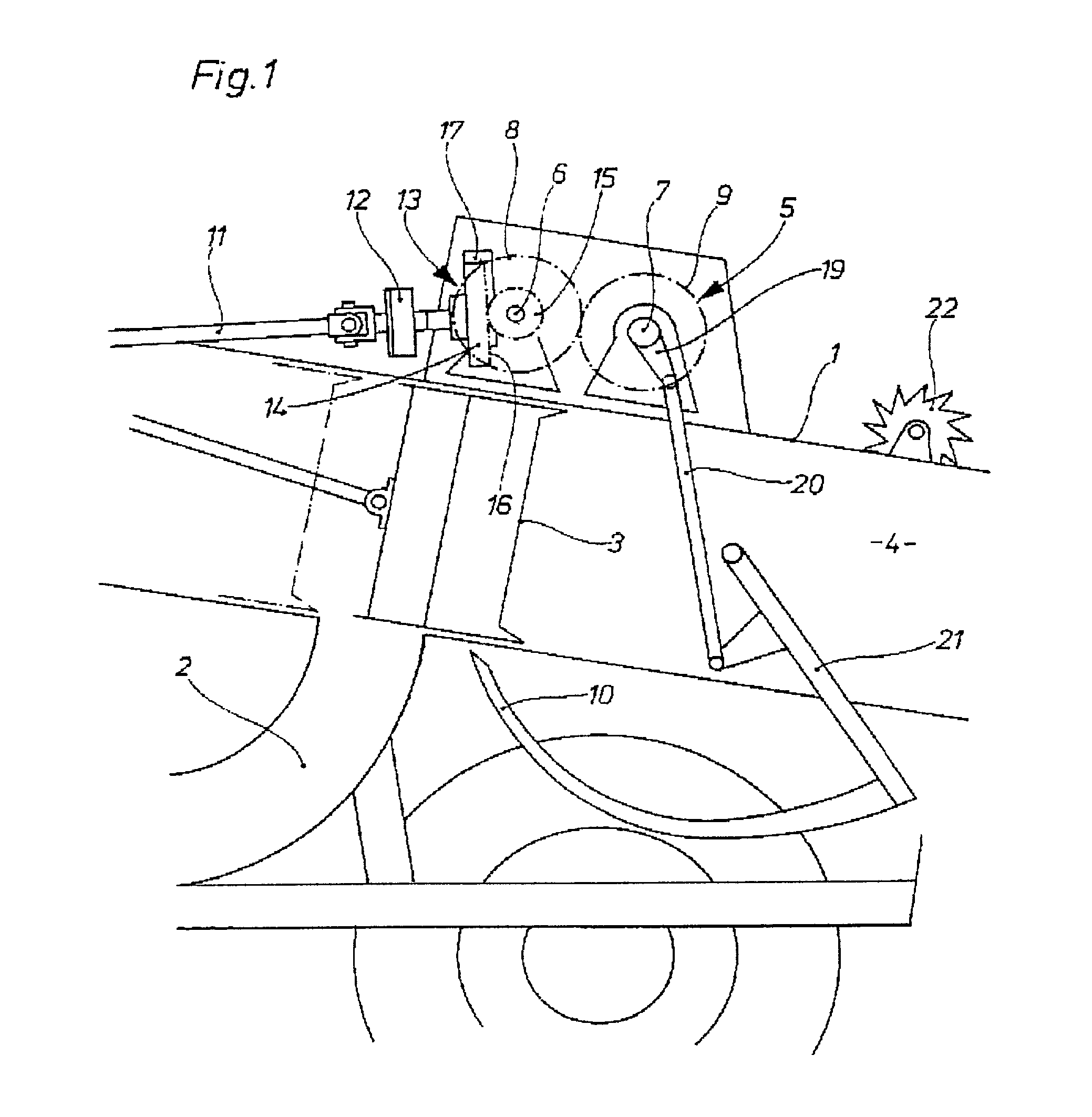
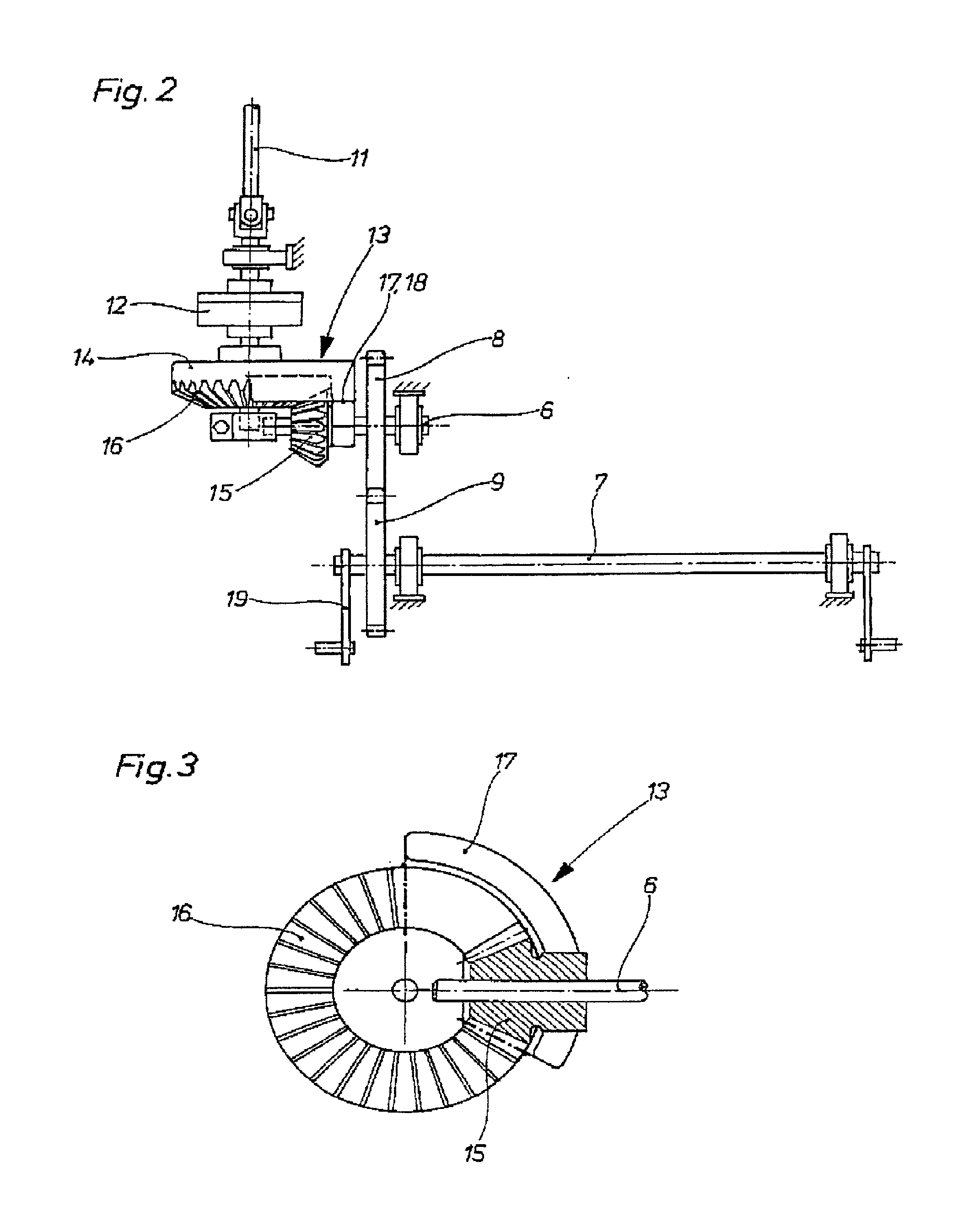
[0029] A big baler 1, which is shown partially in FIG. 1, includes a delivery channel 2, a plunger 3, a baling channel 4, and a binding device 5. The baler 1 cooperates with a twine knotter (not shown) driven by a knotter shaft 7 that extends parallel to a connecting shaft 6 and is driven thereby. Respective spur gears 8, 9, which engage each other and have the same number of teeth, are fixedly secured on the connecting shaft 6 and the knotter shaft 7, respectively. The spur gears 8 and 9 provide for transmission of a rotational movement from the connecting shaft 6 to the knotter shaft 7. The knotter shaft 7 drives twine needles 10 and twine knotters (not shown) that cooperate with respective twine needles 10. The drive transmission is effected from a drive (not shown) by a drive shaft 11. The transmission ratio between the shaft 11 and the drive of the plunger 3 is 1:1. The drive shaft 11 is arranged perpendicular to the connecting shaft 6. A one-stop clutch 12 is mounted on the dr...


PUM


Abstract

A binding device for a baler including at least one twine needle, a knotter shaft for driving the needle, a one-stop clutch for connecting the knotter shaft with the plunger drive and for intermittently driving the knotter shaft, and a transmission unit provided between the one-stop clutch and the knotter shaft and including elements which insure that for one complete revolution of the one-stop clutch, the knotter shaft also performs one complete revolution but with a higher speed than the one-stop clutch.

Description

[0001] 1. Field of the Invention[0002] The present invention relates to a binding device for a baler including at least one knotter and a twine needle driven by the knotter shaft driven by the baler plunger drive, a one-stop clutch for connecting the knotter shaft with the plunger drive and for intermittently driving the knotter shaft, and transmission means provided between the one-stop clutch and the knotter shaft.[0003] 2. Description of the Prior Art[0004] Such knotters are most often used in balers for forming bales of agricultural harvest goods, but they can also be used for forming bales from paper products, paperboards, recyclable products, and the like. Generally, a plurality of knotters are arranged next to each other over the baling channel. When a bale reaches a predetermined length, the knotter secures the bale with twine loops.[0005] All of the presently available on the market balers use a knotter the shaft of which is driven so that the drive ratio between the knotte...

Claims


Application Information

Patent Timeline
Patent Type & Authority Applications(United States)
IPC IPC(8): A01F15/08
CPCA01F2015/0866A01F15/0858
Inventor HONHOLD, JOOST
Owner LELY VERMEER MASCHFAB
Why Eureka
Try Eureka