
Method and apparatus for bucksawing logs

a technology for buckwheat logs and methods, applied in woodworking apparatus, discharging equipment, manufacturing tools, etc., can solve the problems of low throughput and not particularly well suited to modifying methods

Inactive Publication Date: 2002-06-13
MURRAY ROBERT JAMES
View PDF0 Cites 13 Cited by
  • Summary
  • Abstract
  • Description
  • Claims
  • Application Information

AI Technical Summary

Benefits of technology

0032] FIG. 26 is a detail elevation view of the multi-positional cut-off saw and conveyor shown in FIG. 20, with the cut-off saw assembly not shown for ease of illustration;
0033] FIG. 27 is a plan view of a further embodiment of the

Problems solved by technology

This method is not particularly well suited to modifying the position of the cross cut to maximize the value and recovery from the log.
This method is better at maximizing the value and recovery from the log, but in both this method and the transverse method the speed of the transport conveyor is necessarily fixed at the speed the log moves through the sawing station, resulting in low throughput.

Method used


Image

  • Method and apparatus for bucksawing logs
  • Method and apparatus for bucksawing logs
  • Method and apparatus for bucksawing logs

Examples


Embodiment Construction

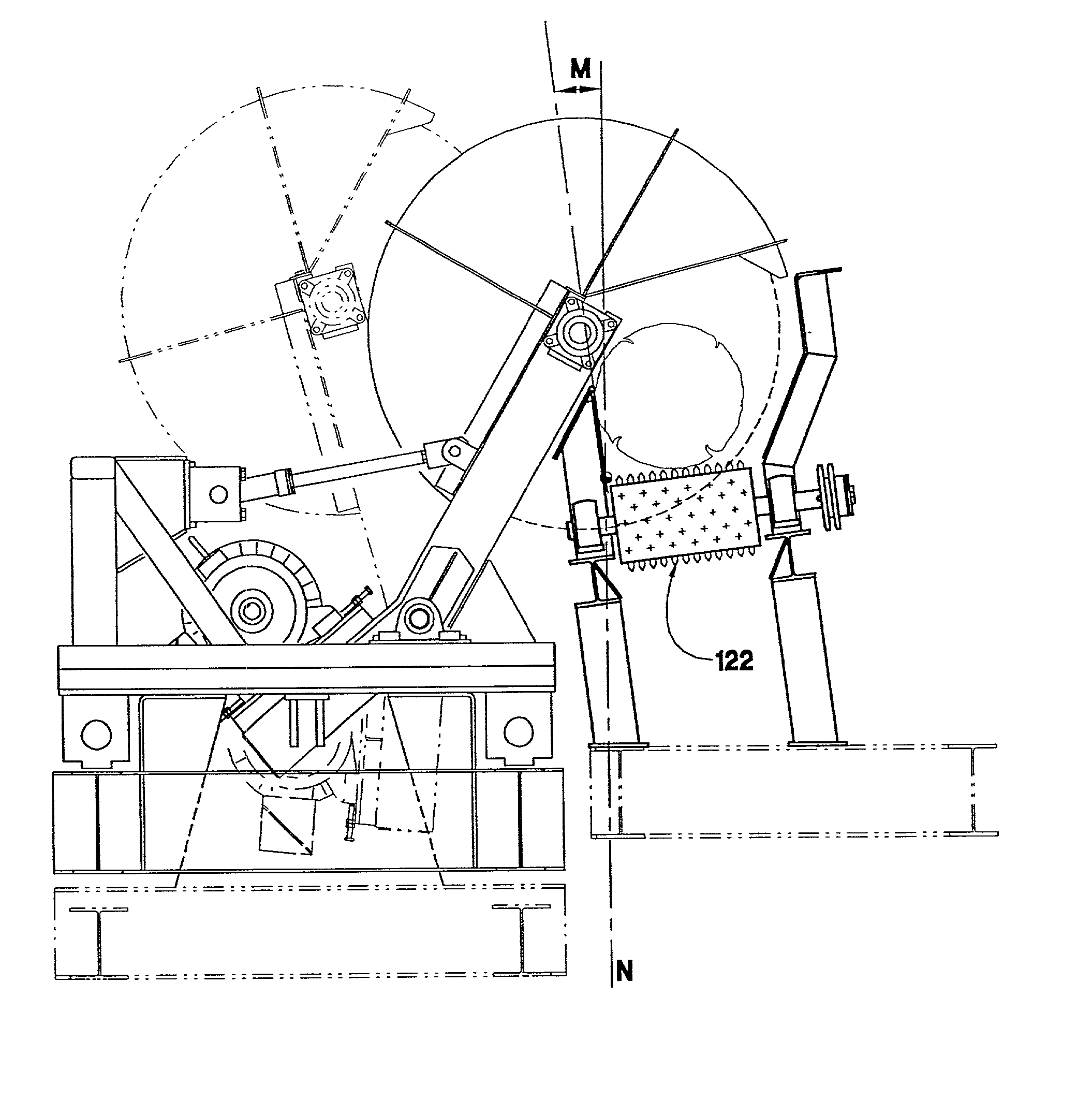
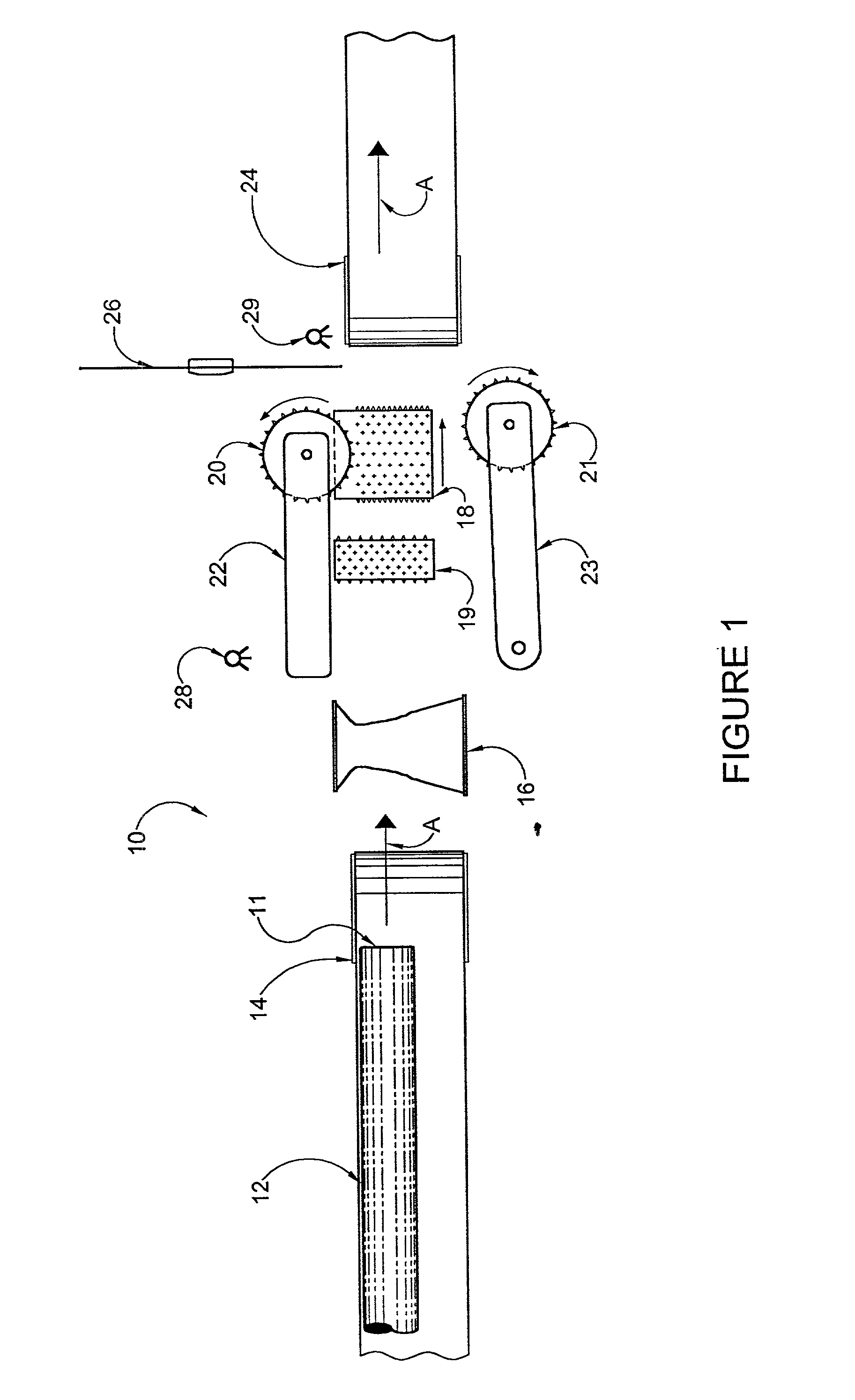
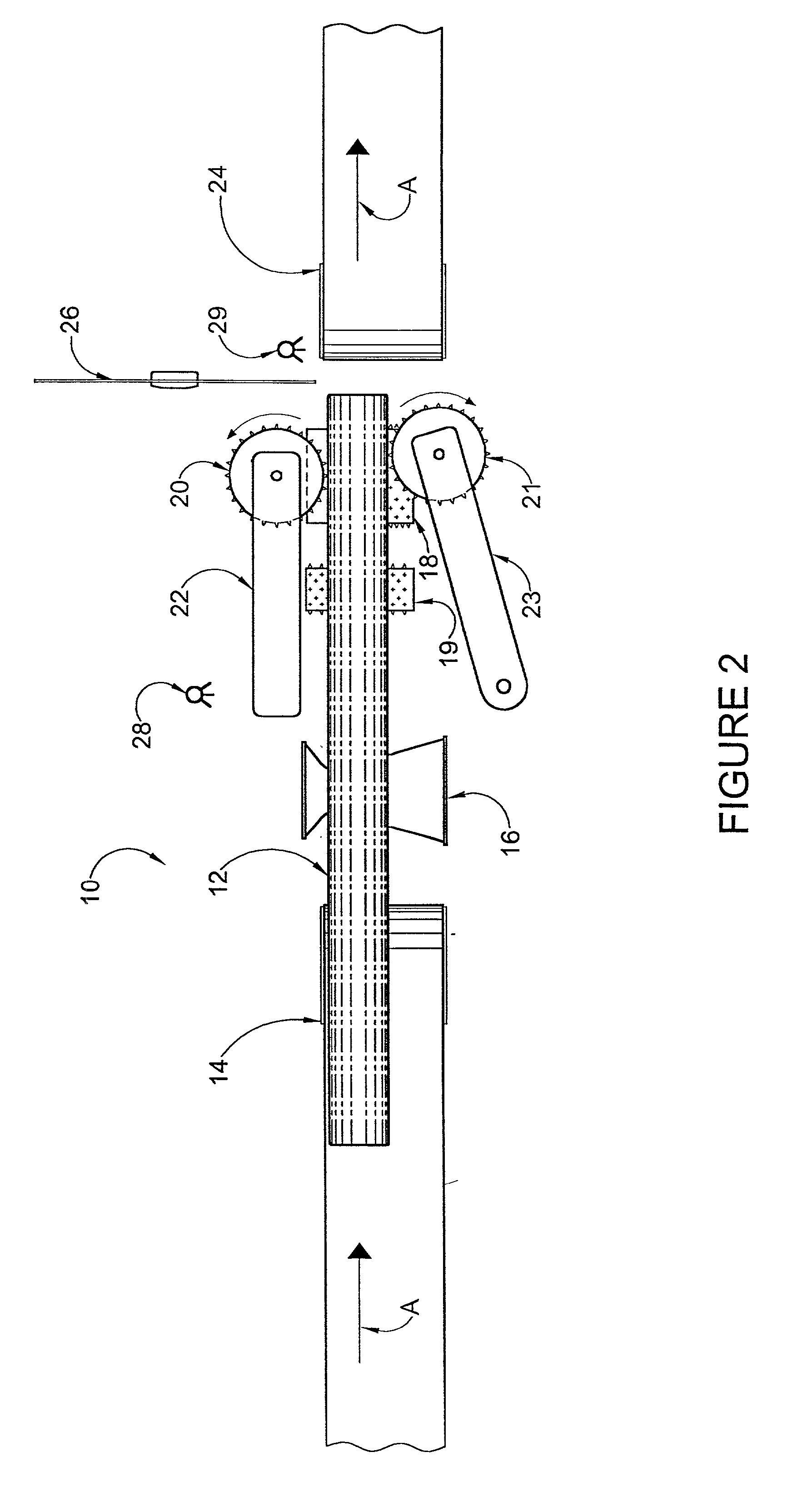
[0035] Looking at FIG. 1, the bucksawing apparatus, designated generally as 10, has a log 12 moving in the direction of arrow A on tilted infeed conveyor 14 towards a powered hourglass roll 16, tilted bottom feed rolls 18 and 19 and tilted side feed rolls 20 and 21. The degree of tilt of the conveyors and feed rolls is sufficient to cause the logs to roll to the proper feed line. As shown in FIG. 10, a degree of tilt M of 7 degrees from the vertical N has been found to be optimal. By uniformly tilting the infeed and outfeed conveyors and feed rolls by about 7 degrees, the log 12 is aligned against a barrier or guide to line up with feed roll 20 on fixed arm 22, so only one arm 23 need pivot. Feed rolls 18, 19, 20 and 21 are provided with spikes 25 (see FIG. 6 and 7) to grip the log 12 without slippage, and are rotatably driven by vector duty electric motors 80 with encoders 81 (see FIG. 6 and 7) through planetary gear reducers 70. The rotary motion of the output shaft of the planeta...


PUM

PropertyMeasurementUnit
Angleaaaaaaaaaa
Lengthaaaaaaaaaa
Diameteraaaaaaaaaa

Abstract

Previous methods of bucksawing logs slow the throughput of a sawmill in that the conveyor line is stopped while a given log is bucksawed to length. The present invention provides a method for bucksawing a log which improves the throughput speed. The present invention provides a method and apparatus for bucksawing a log comprising the steps of a) advancing the log endwise along a tilted infeed conveyor; b) positioning the log on a tilted feed roll above the level of an outfeed conveyor while advancing the log; c) measuring the advance of the log while on the tilted feed roll; d) stopping the log at the desired length; e) sawing the log to produce a forward log segment; f) moving the forward log segment onto a tilted outfeed conveyor while advancing the remaining log segments. The present invention further provides a method and apparatus for bucksawing a log comprising utilizing a second multi-positional cut-off saw in the bucksawing station. The present invention further provides a method for bucksawing a log comprising utilizing a shifting gap in the conveyor system associated with the second multi-positional cut-off saw in the bucksawing station. The present invention further provides a method and apparatus for bucksawing a log comprising utilizing two multi-positional cut-off saws in the bucksawing station for indefinite length cuts.

Description

[0001] This application is a continuation-in-part of United States patent application Ser. No. 09 / 302,180 filed Apr. 30, 1999 which is pending.[0002] The invention relates to apparatus for cross-cutting or "bucksawing" long logs to produce logs of shorter length. More particularly the invention relates to a method and apparatus for feeding, positioning and holding a log for bucksawing to the desired length.[0003] It is important in the sawing of logs into lumber that the selection of saw cuts be made to maximize the quantity and quality of lumber which is yielded by the log, depending on the length, thickness and quality of the log, such as the presence of knots, defects and the like. As the first step in this process, the tree-length log is cut into shorter lengths, or "bucked", prior to further processing. There are 'two commonly used methods of carrying this out in a sawmill. A first method is a transverse system whereby the tree-length log is moved sideways through a battery of ...

Claims


Application Information

Patent Timeline
IPC IPC(8): B27B1/00B27B5/18B27B25/02B27B31/00B27B31/08
CPCB27B1/002B27B5/185B27B5/187B27B31/08B27B31/003B27B31/006B27B25/02Y10T83/54Y10T83/6539
Inventor MURRAY, ROBERT JAMES
Owner MURRAY ROBERT JAMES
Learn More