
Molded composite structure and method of forming same

a composite structure and molded technology, applied in the direction of process and machine control, mechanical control devices, instruments, etc., can solve the problems of direct impact on the ability of the wing structure to perform these functions, the ability of the aircraft to take off and land, and the ability to change speed and direction,

Inactive Publication Date: 2002-06-13
TOYOTA MOTOR CO LTD
View PDF17 Cites 48 Cited by
  • Summary
  • Abstract
  • Description
  • Claims
  • Application Information

AI Technical Summary

Problems solved by technology

Finally, the cost of manufacturing the wing structures has a large impact on the overall manufacturing cost of these airplanes.
For example, the smoothness and weight of the wing structures directly impacts the wing structures ability to perform these functions.
In particular, the smoothness of the exterior of the wing structures affects the ability of the aircraft to take off and land, to change speed, and to change direction.
If a wing structure has an uneven or non-smooth surface, this can create unnecessary drag, affecting the ability of the wing structures ability to perform many of the key functions.
The aircraft will not be able to take off and land as easily, and it will be more difficult to alter the speed and direction of the plane during flight.
The weight of the wing structures also impacts the ability of the aircraft to take off and land, to change speed, and to change direction.
The heavier the wing structures are, the more difficult it will be for the aircraft to take off and land.
Further, heavier wing structures also make it more difficult to alter the speed and direction of the aircraft during flight.
If the wing structures are not designed to be aerodynamically sound, this smooth laminar flow will be disrupted.
For example, if the wing structures do not have a smooth surface, added drag could result on portions of the wing structures.
This will therefore increase the amount of fuel needed for flight.
The cost of manufacturing the wing structures also depends on the design and construction of the aircraft.
The cost of the material used to manufacture the wing structures as well as the labor costs of manufacturing the wing structures greatly impacts the overall cost of the wing structures.
However, the manufacture of wing structures from aluminum is labor-intensive.
A large amount of time is spent in manufacturing and assembling the aluminum sheets.
In addition, while aluminum is a light-weight metal, it is heavier than other non-metal materials that could be used.
Therefore, it causes the wing structure to be unduly heavy.
Finally, the mechanical attachments associated with aluminum wing structures decrease the smoothness of the wing structure.
However, like aluminum, constructing wing structures using wet lay-up composite materials is labor-intensive and expensive.
The process of forming composite materials into the shape of a wing structure with this method requires complicated machining and tooling.
Further, while composite materials are lighter than other materials, the wet lay-up process requires the use of a large amount of composite material.
This increases the weight of the wing structures and thereby affects the performance of the wing structures.
However, unlike aluminum and composite materials, the construction of wing structures from hand laid-out prepreg is not labor-intensive.
However, prepreg is very expensive.
Therefore, this method greatly increases the manufacturing costs.

Method used


Image

  • Molded composite structure and method of forming same
  • Molded composite structure and method of forming same
  • Molded composite structure and method of forming same

Examples


Embodiment Construction

[0062] A. Introduction

[0063] Methods and structures in accordance with the present invention will now be described with respect to an embodiment of a molded composite structure, an aircraft wing panel. The invention as claimed, however, is broader than wing panels and extends to other molded composite structures, such as, for example, a full wing structure, inserts, controls, empennages, fuselages, and stabilizers. In addition, the invention as claimed, is broader than aircraft structures and extends to automotive, forklift, watercraft, and building structures.

[0064] B. Methods and Structures

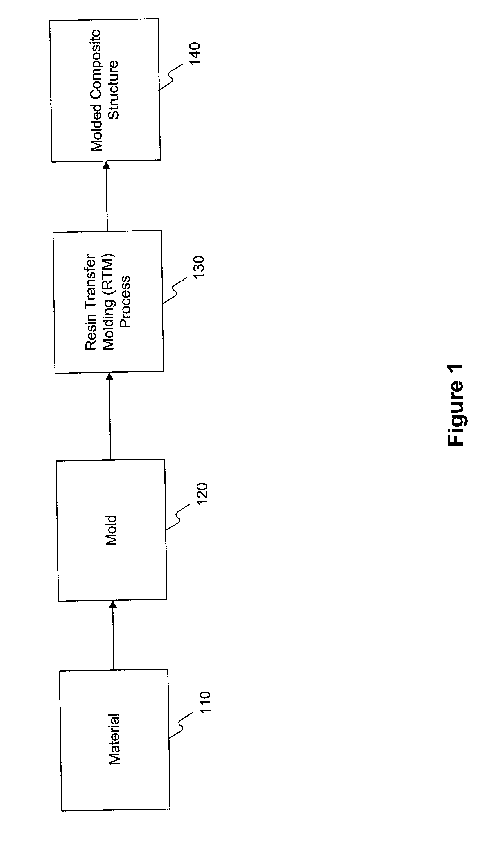
[0065] FIG. 1 is a block diagram illustrating the components for manufacturing a molded composite structure consistent with an embodiment of the invention. As shown in FIG. 1, the integration of a material (block 110), a mold (block 120), and a Resin Transfer Molding ("RTM") process results in a molded composite structure 140 (for example, a wing panel).

[0066] Block 110 includes the selection an...


PUM

PropertyMeasurementUnit
Temperatureaaaaaaaaaa
Pressureaaaaaaaaaa
Structureaaaaaaaaaa

Abstract

A molded composite structure and a method of manufacturing a molded composite structure are disclosed. In one embodiment, an aircraft wing panel and a method for manufacturing an aircraft wing panel are disclosed. In another embodiment, the method of manufacturing a molded composite structure uses a resin transfer molding process.

Description

I. CROSS-REFERENCE TO RELATED APPLICATION[0001] This application claims the benefit of U.S. Provisional Application No. 60 / 254,080, filed Dec. 8, 2000, titled A SMOOTH LAMINAR FLOW STRUCTURE AND METHOD OF FORMING SAME, the disclosure of which is expressly incorporated herein by reference.II. BACKGROUND OF THE INVENTION[0002] A. Field of the Invention[0003] The present invention relates to a molded composite structure and a method of manufacturing a molded composite structure.[0004] B. Background of the Invention[0005] In general, most airplanes comprise a number of components such as a fuselage, an empennage, and wing structures. Wing structures are particularly important in the construction of airplanes because wing structures are the primary lift-producing structures and perform some of the key functions for these airplanes. For example, wing structures enable airplanes to take off and land, to change speed, and to change direction, as well as other functions. Furthermore, as one ...

Claims


Application Information

Patent Timeline
IPC IPC(8): B29C70/08B29C70/44
CPCB29C70/086B29C70/443Y02T50/433B29L2031/3085B32B27/08B29C70/543Y02T50/40
Inventor MAXWELL, MICHAEL K.GARDINER, RICHARD J.
Owner TOYOTA MOTOR CO LTD
Learn More