Patient movement detection apparatus

a technology for movement detection and patient, applied in the field of patient movement detection apparatus, can solve the problems of reducing the efficiency of patient movement detection, and reducing the accuracy of switch based systems, so as to optimize the performance of hysteresis, the effect of minimizing the effect of potential

Inactive Publication Date: 2002-06-13
STRYKER CORP
View PDF0 Cites 85 Cited by
  • Summary
  • Abstract
  • Description
  • Claims
  • Application Information

AI Technical Summary

Benefits of technology

0006] The present invention includes a first embodiment of a patient movement detection apparatus comprising a plurality of load cell discs for placement under a support member of a patient support device such as a leg of a bed, a chair or a wheel chair. The load cell discs are placed in compression through a force applied by the support member of the patient support device. The load cell disks contain a plurality of strain gages for measuring compression and tensile stresses placed on the strain gages during shifting of a patient's center of gravity on the patient support device. A placement and an arrangement of the strain gages within a structure of the load cell disks helps to minimize the effect of a potential off-center or a side load introduced onto the load cell disks by the support member. The structure of the load cell disk is also optimized for hysteresis performance and the minimization of thermal expansion and compression due to temperature.

Problems solved by technology

For example, a patient who is physically capable of leaving the bed but who is subject to dizziness upon standing up might fall and injure himself if he leaves the bed when no attendant is present.
The switch could be connected in a series circuit with a source of power such as a battery and with an alarm such as a buzzer, and would thus produce audible noise when the patient left the bed.
Switch based systems were often inaccurate and often presented a false alarm condition where the patient either had not substantially moved within the patient support device or had already substantially left the support device prior to alarming.
While known systems of this type have been adequate for their intended purposes, they have not been satisfactory in all respects.
Such systems can be expensive and are often cost prohibitive for many health care operations.

Method used


Image

  • Patient movement detection apparatus
  • Patient movement detection apparatus
  • Patient movement detection apparatus

Examples


first embodiment

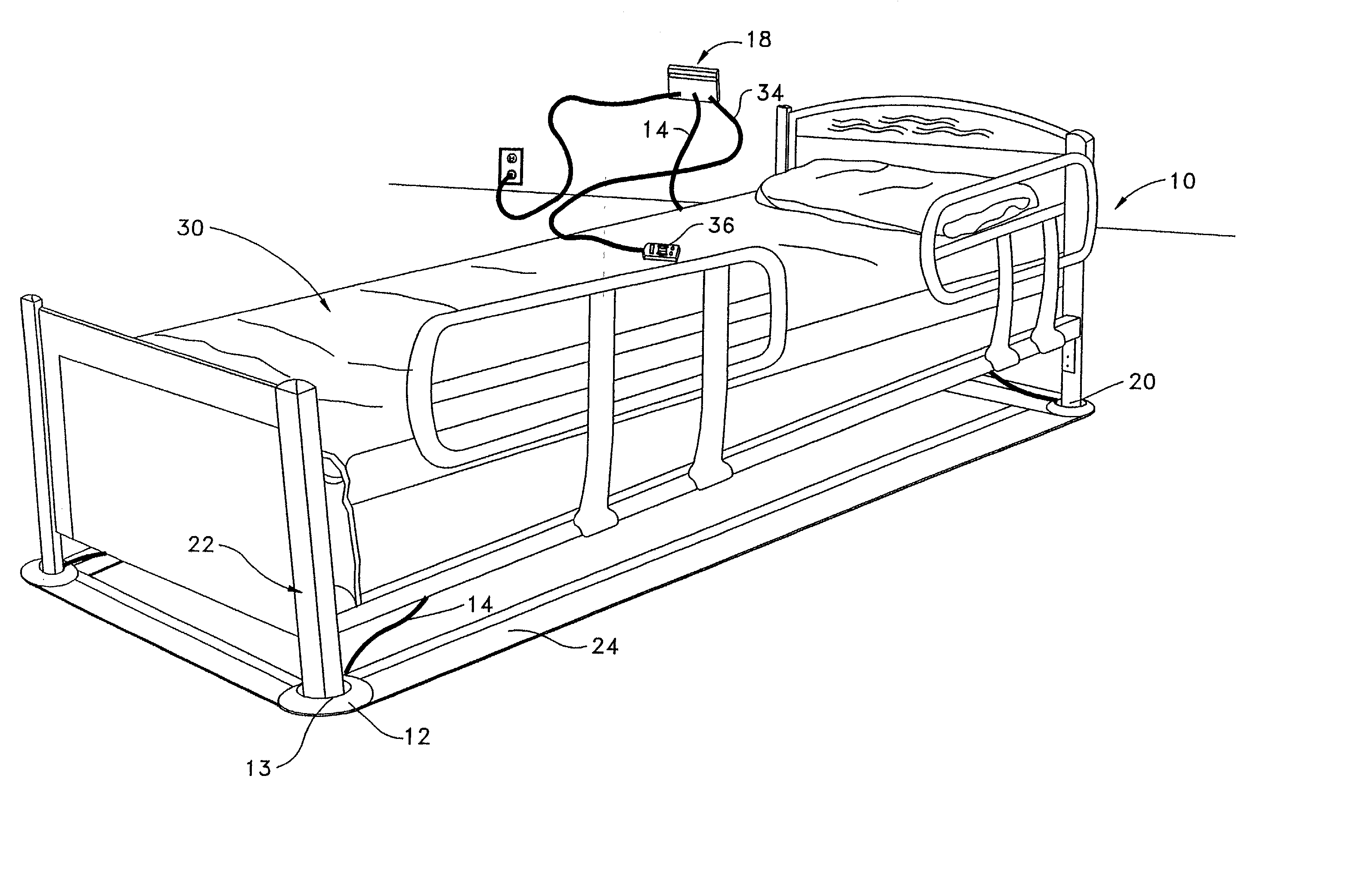
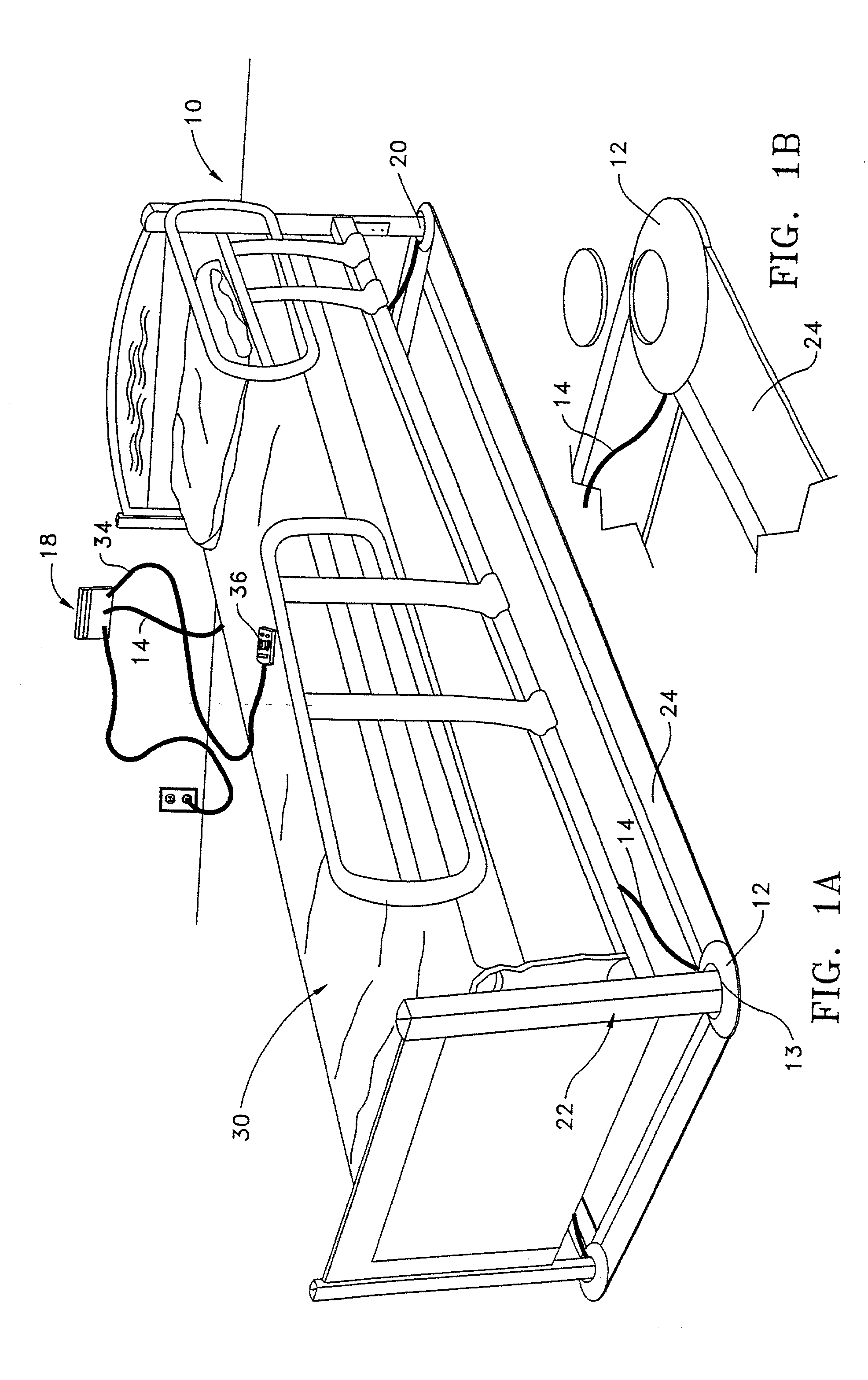
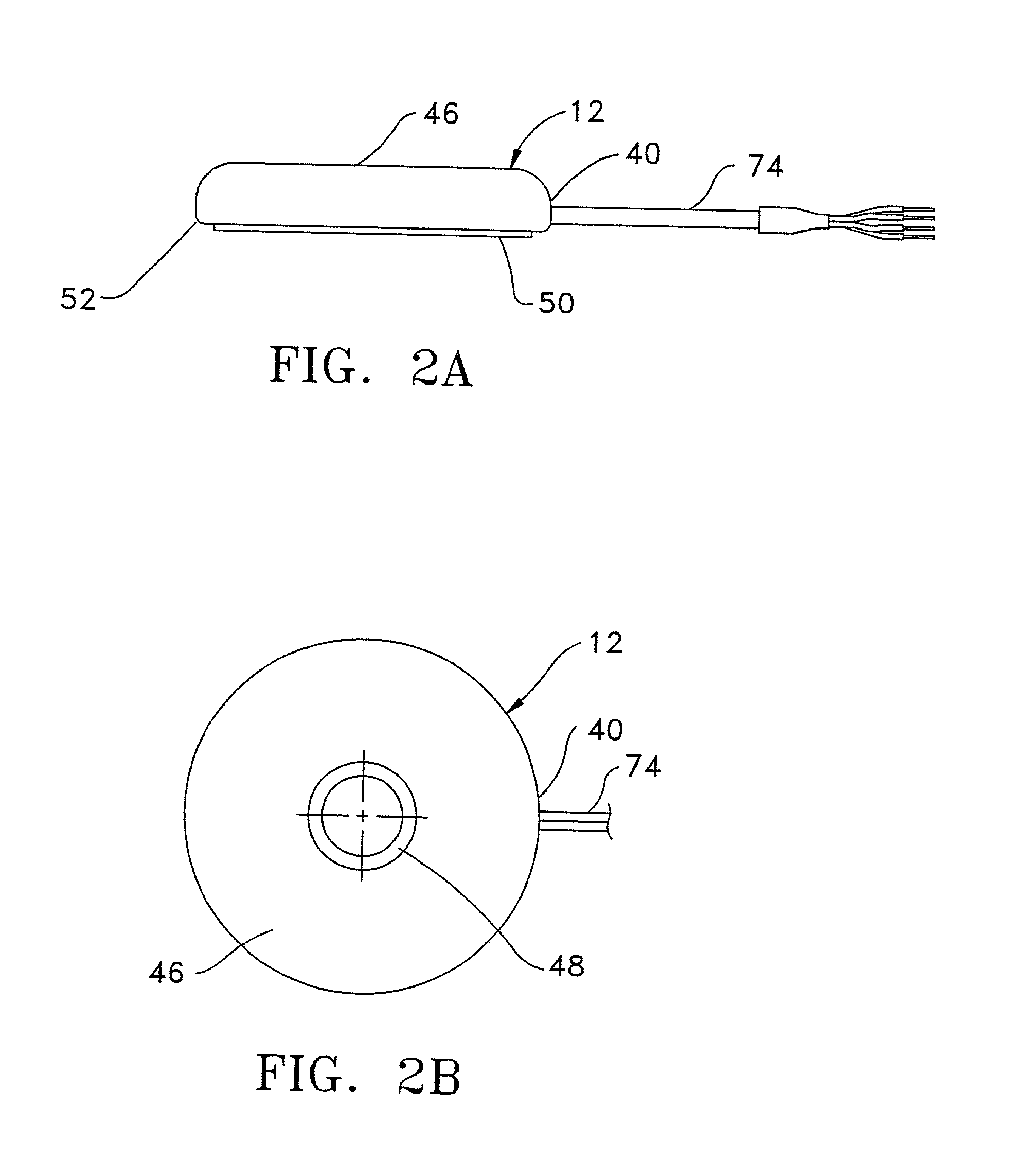
[0023] Referring to the Figures wherein like numerals indicate like or corresponding parts throughout the several views, in FIG. 1A a load cell disk patient movement detection apparatus of a first embodiment is shown generally at 10. The apparatus 10 is shown attached to a patient support device 30 comprised of a plurality of support members 20 and a plurality of structural members 22. The patient support device 30 shown in FIG. 1A is a bed. Alternatively, the patient support device 30 could be a chair or a wheel chair or any patient support device that supports a body of a patient in a health care setting. The apparatus 10 comprises a plurality of load cell disks 12 placed under the support members 20 of the patient support device 30. The patient support members 20 apply a compressive load to a top portion 13 of the load cell disks 12. A plurality of transmission cables 14 are attached to the load cell disks 12 for transmitting a signal generated by the load cell disks 12 to a comb...

second embodiment

[0027] In FIG. 3A a load cell beam patient movement detection apparatus of a second embodiment is shown generally at 100. The apparatus 100 is shown attached to a patient support device 150 comprised of a plurality of support members 120 and a plurality of structural members 122. The patient support device 150 shown in FIG. 3A is a bed. Alternatively, the patient support device 150 could be a chair or a wheel chair or any patient support device that supports a body of a patient in a health care setting. The apparatus 100 comprises a plurality of load cell beams 112 placed partially under an end 140 of the support members 120 of the patient support device 150. The patient support members 120 apply a shear load to the load cell beams 112. A plurality of transmission cables 114 are attached to the load cell beams 112 for transmitting a signal generated by the load cell beams 112 to a combination processing unit / peripheral communication device 118. Alternatively, (not shown) the combina...

third embodiment

[0034] In FIG. 6A a load cell column patient movement detection apparatus of a third embodiment is shown generally at 400. The load cell column patient movement detection apparatus 400 comprises a plurality of load cell columns 410 mounted to a patient support device (not shown) by a mounting bracket 420. The load cell columns 410 are attached to the mounting bracket 420 by a fastener 440. When in place, the load cell columns 410 serve as a leg of a patient support device providing partial support of the patient support device. The load cell columns 410 comprise a plurality of strain gages (not shown) for reacting to the compression and tension forces applied to the load cell columns 410 by the patient support device. Attached to a bottom 450 of the load cell columns 410 is a rubber or synthetic cap providing a soft base for the load cell columns 410.

[0035] In FIG. 6B a load cell column 410 is shown with a transmission cable 460 attached for transmitting a signal generated by the lo...


PUM


Abstract

A patient movement detection device is provided comprising a plurality of load cell disks, beams, or columns placed under a support member of a patient support device. The load cells are connected to a processing unit by a plurality of transmission cables. The processing unit is connected to a peripheral communication device. A method of detection of movement of a patient is provided comprising the steps of generating a signal by a load cell disk or beam when a change in a patient's center of gravity occurs on the patient support device, transmitting the signal to a processing unit, and further transmitting the signal to the peripheral communication device.

Description

[0001] The present invention relates to an arrangement for detecting patient movement within a patient support device such as a hospital bed, chair, wheel chair or similar support structure and, more particularly, to a load cell center of gravity based arrangement capable of detecting patient movement while a substantial portion of the patient's weight is still supported on the patient support device.[0002] In a health care setting, it is sometimes necessary to monitor a patient in order to help ensure that the patient remains in a patient support device such as a bed, a chair, a wheel chair or the like. For example, a patient who is physically capable of leaving the bed but who is subject to dizziness upon standing up might fall and injure himself if he leaves the bed when no attendant is present. Consequently, it is desirable that an alarm be given in the event the patient leaves the bed so that a member of a health care staff will be alerted to the fact that the patient has left ...

Claims


Application Information

Patent Timeline
Patent Type & Authority Applications(United States)
IPC IPC(8): A61B5/11G08B21/04
CPCA61B5/11G08B21/0461G08B21/0446
Inventor CONWAY, KEVIN P.KRAMER, KENNETH L.VALDES, CARLOS E.
Owner STRYKER CORP
Why Eureka
Try Eureka