Open type wedgethread connection

Inactive Publication Date: 2002-06-20
RAMOS BEVERLY WATTS
View PDF0 Cites 13 Cited by
  • Summary
  • Abstract
  • Description
  • Claims
  • Application Information

AI Technical Summary

Benefits of technology

0047] It is a further object of the present invention to provide an Open wedgethread that is highly resistant to handling damage during manufacture, shipment and installation, in that no sharp corners exist between the metal faces forming the corners, but have crests positioned at approximately 90 degrees to the flanks connected, by generous radii so as to thereby survive reasonable handling without significant damage. To even further minimize effects of localized crest damage too small to notice visually during assembly, the present invention teaches that the thread flank widths be dimensioned and toleranced such that the pin roots contact the box crests upon assembly but hold the pin crests which are most subject to damage, apart from the box roots so as to prevent interference and galling there between. It is within the scope of the present invention for the box roots to contact the pin crests and for the pin roots be held apart from the box crests, but this damage prevention feature would be lost along with the best sealing configuration, explained as follows: At the small diameter end of thread engagement, the axial length of the pin root-box crest contact of a wedgethread is necessarily much longer than the axial length of the pincrest-boxroot contact, so my preferred embodiment provides that the longer length pinroot-boxcrest lengths be in certain intimate contact to minimize leak tendency there where fluid pressure is typically the greatest, and that the shorter lengths define a gap not greater than the bridge dimension, to be sealed by thread dope. So as to help maintain the previously discussed intimate pinroot-boxcrest contact after make-up of the connection, a predetermined amount of radial interference is preferred to exist between the box and pin threads sufficient to generate an optimum tension hoop stress in the box and a compressive hoop stress in the pin. Should box makeup hoop stress be excessive, then the connections rating against internal fluid pressure could be reduced, or should pin makeup hoop stress be excessive, then the connections rating against external fluid pressure could be reduced because such stresses are additive to hoop stresses generated by fluid pressures. Therefore, the present invention teaches that the preferred diametrical interference between the mating box and pin threads should approximate the quantity: 1/3 times the pipe O.D. times the pipe material yield strength, divided by the pipe material modulas of elasticity. For best performance, thread interference should extend all along the helical thread length to both ends of the engaged threads, which should be considered when diameter and taper tolerances are specified. Such a controlled interference should allow reliable service near maximum ratings.
0048] For extreme service requirements or because a user specification requires it, metal-to-metal seals to augment or replace the thread seal, may be provided adjacent either or both ends of the engaged threads. Most often, such a sealing surface is positioned adjacent the pin end for cooperation with a mating sealing surface formed within the box adjacent the small diameter end of the box threads, so as to reduce the sealing diameter against internal fluid pressure to a minimum and thereby, reduce the fluid pressure load on the connection to a minimum. Occasionally it may be required to provide a metal-to-metal seal adjacent the large diameter end of the mating threads by forming an inner diameter surface of the box adjacent it's end for cooperation with a mating sealing surface formed around the pin adjacent the large diameter end of the pin threads.

Problems solved by technology

It is generally known that entrapment of excess dope between any type mating threads can cause major problems.
Industry experts have long held that to prevent thread jump-out, a negative thread flank angle was necessary and have therefore devised many complicated, expensive and hard to inspect thread designs, as the above cited trapped wedgethread patents disclose.
When a conventional pin having a relatively thin wall is made up into a box having a much thicker wall, then a jump-out tendency may exist because upon application of high axial tension loads, the thin pin wall tends to contract radially according to Poisson's ratio more than the

Method used


Image

  • Open type wedgethread connection
  • Open type wedgethread connection
  • Open type wedgethread connection

Examples


Embodiment Construction

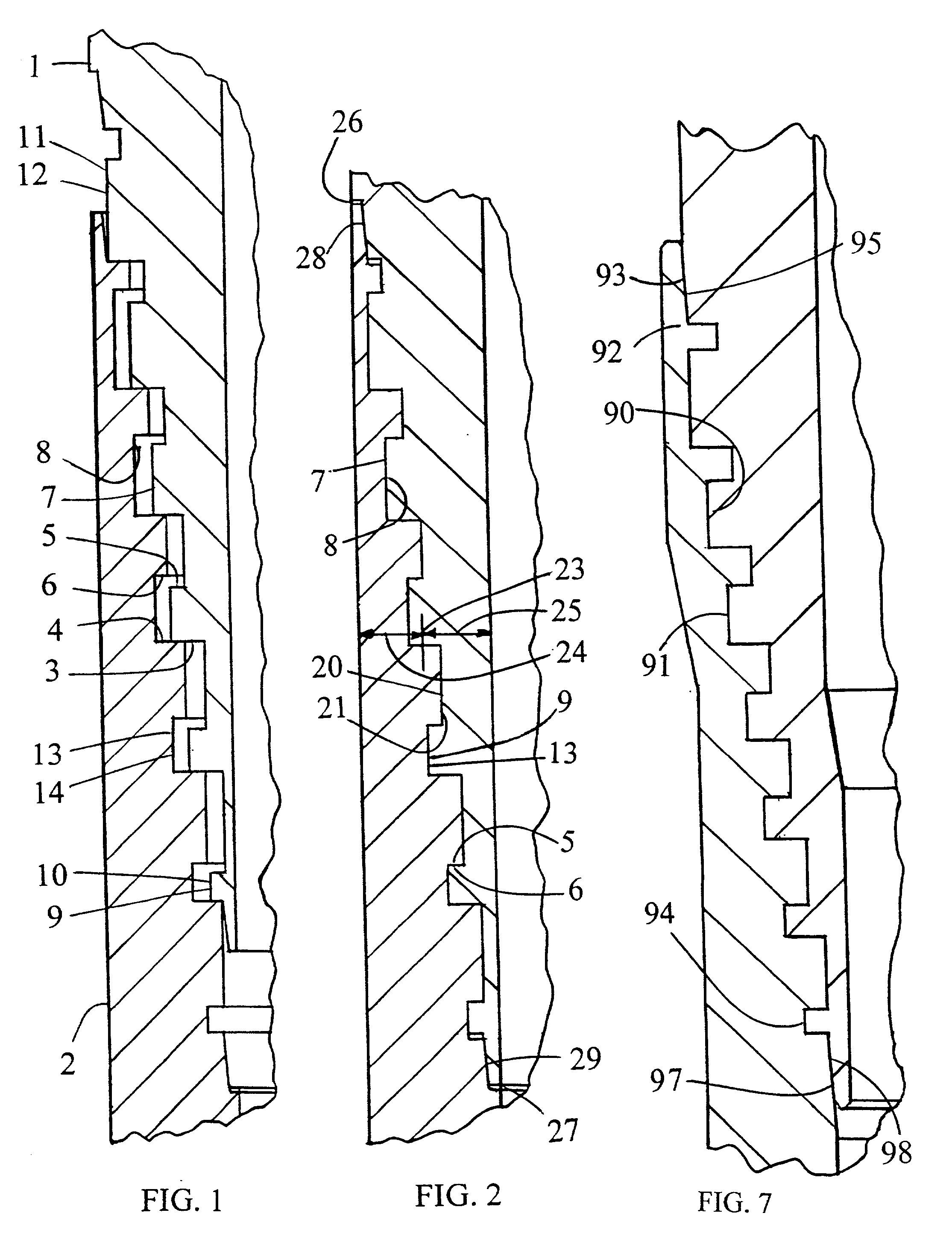
[0094] Multiple-start wedgethreads are within the scope of the present invention but for brevity, only a one-start thread is described. FIG. 1 depicts Pin 1 at stab position within Box 2 such that helically configured pin stab flank 3 and the weight of the pipe joint it is formed on, is supported by helically configured box stab flank 4. Pin load flank 5 and box load flank 6 are not then in contact with each other. Stab position is attained by lowering the pin into the box without rotation, wherein thread turns of the pin pass downwardly through thread turns of the box until the pin stab flank of each turn contacts a box stab flank turn too small in diameter for it to pass through, such that the pin stab flank rests on the box stab flank whereupon, pin crest 7 is in horizontal alignment within box root 8. Both root and crest are preferably formed parallel to the connection axis so as to prevent taper lockup during stabbing and also, to provide wider flanks. Axial length 9 and diamet...


PUM


Abstract

An open wedgethread is disclosed that has an included angle measured in the gap between the stab flank and the load flank to be not less than zero, so as to prevent premature wedging between mating flanks before the position of full makeup is reached, as does occur between trapped wedgethreads wherein the included angle is less than zero. The invention may be used for pipe threads large or small, as a flush joint, with collars, screwed into plates or it may even be used to reversibly connect such as solid posts to base members where a wide makeup torque range is desired. This Open wedgethread, as opposed to trapped wedgethreads, provides a threaded pipe connection that: is more cost-effective; can seal high pressure gas; can provide selectively a connection strength as high as the pipe strength; assures easy makeup to the desired position of full makeup within a wide torque range; may have a torque strength as high as the pipe torque strength; is easier to manufacture; is easier to gage; and is less subject to handling damage.

Description

[0001] This Application is a Continuation of application Ser. No. 09 / 573,480 filed May 16, 2000, which was a Continuation-In-Part of application Ser. No. 09 / 421,483 filed Oct. 20, 1999, for the Non-Elected Invention thereof.TECHNICAL FIELD[0003] The use of conventional screw threads to connect joints of pipe together so as to convey fluid, is a very old art that has progressed for hundreds of years in an effort to satisfy periodic needs for stronger and better sealing pipe connections. Performance requirements for pipe connections still vary widely today, such as for home piping with less than 80 psi fluid pressure with virtually no mechanical loads, to Oil Well Pipe that may be required to hold over 15,000 psi gas pressure and simultaneously, withstand extreme mechanical loadings and endure wide temperature fluctuations. The use of conventional screw threads to connect structural members is also an old art.[0004] Due to the historical weakness of threaded pipe connections and their...

Claims


Application Information

Patent Timeline
IPC IPC(8): F16LF16L15/00F16L15/06F16L25/00
CPCF16L15/001E21B17/042
Inventor WATTS, JOHN D.
Owner RAMOS BEVERLY WATTS
Why Eureka
Try Eureka