Flow cytometer

a flow cytometer and flow cytometer technology, applied in the field of flow cytometers, can solve the problems of not rotating smoothly without vibration, the peak level and pulse width of particle detection signals may not be correctly obtained, and the peak level and pulse width of particle detection signals may not be smooth

Inactive Publication Date: 2002-06-27
SYSMEX CORP
View PDF1 Cites 43 Cited by
  • Summary
  • Abstract
  • Description
  • Claims
  • Application Information

AI Technical Summary

Problems solved by technology

However, as the stepping motor rotates in units of step angles such as 1.80 or 0.90, it does not rotate smoothly without vibration.
Further, the fluctuation signal and ...

Method used


Image

  • Flow cytometer
  • Flow cytometer
  • Flow cytometer

Examples


Embodiment Construction

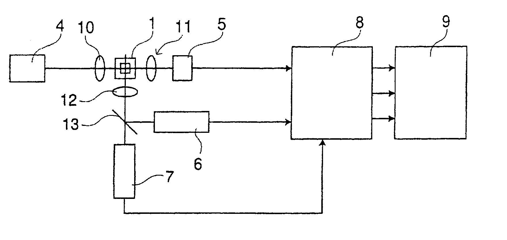
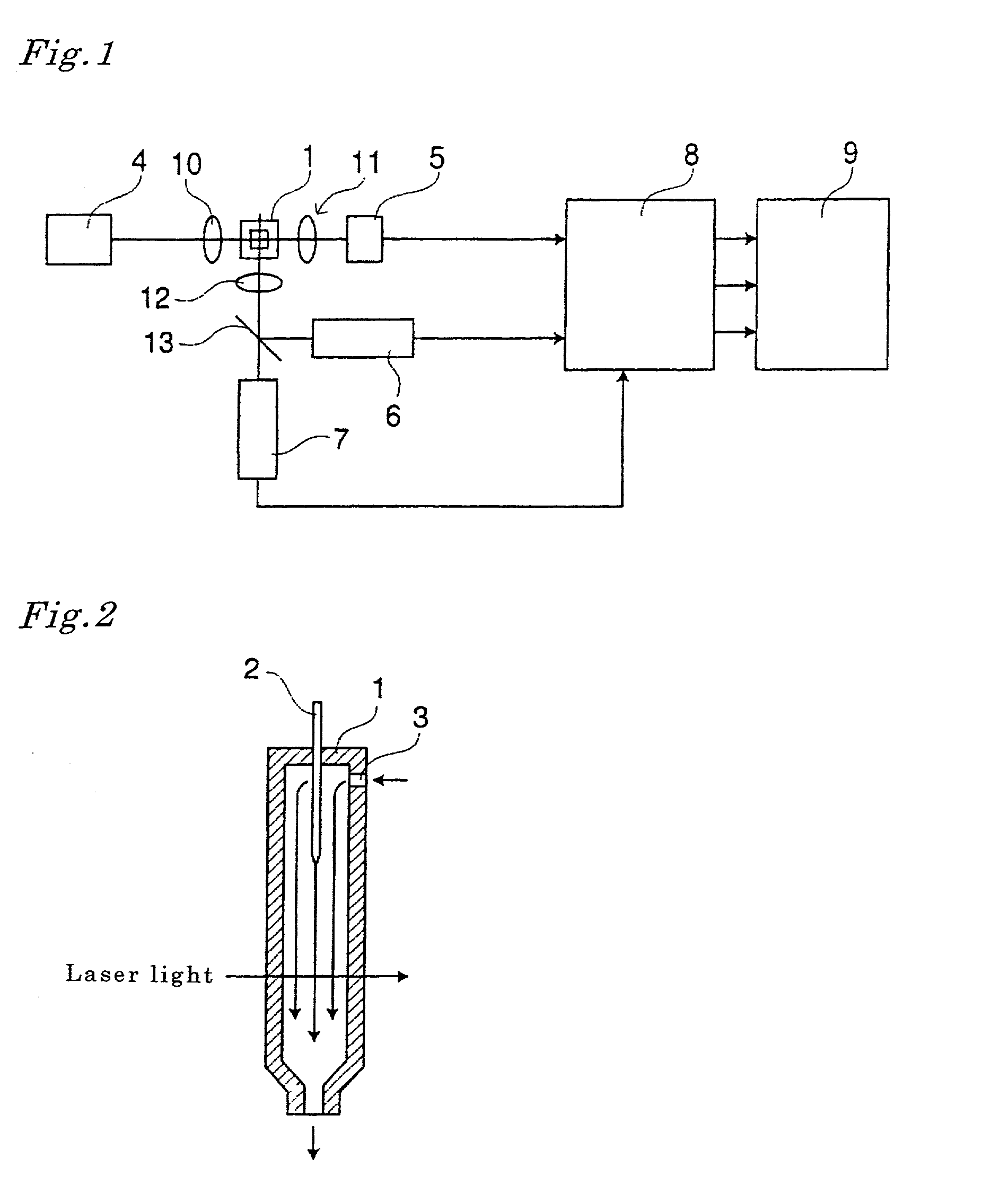
[0026] This invention relates to a flow cytometer comprising a sheath flow cell for surrounding a sample solution containing a particle with sheath liquid and forming a sample solution flow, a light source for radiating light to the sample solution flow, a detecting part for detecting optical information from a particle contained in the sample solution flow and converting it to an electric signal, and a signal processing part for processing an electric signal outputted from the detecting part. Further, this cytometer may have an analyzing part for analyzing characteristics of a particle from the electric signal detecting part or signal processing part outputs.

[0027] The subjects the flow cytometer measures according to this invention are mainly bacteria and blood cells contained in urine, and particles in various tissues. However, the subjects may be blood cells contained in blood, etc., in a specimen, microorganisms such as yeast and lactic bacteria, and industrial powders.

[0028] T...


PUM


Abstract

A flow cytometer includes a sheath flow cell for forming a sample solution flow by surrounding sample solution containing particles with sheath liquid, a light source for radiating light to the sample solution flow, a detecting part for detecting optical information from particles contained in the sample solution flow and converting it to electric signals, and a signal processing part for extracting fluctuation signals from the electric signals which the detecting part outputs.

Description

[0001] This application relates to Japanese Patent Application No. 2000-391182 filed on Dec. 22, 2000 whose priority is claimed under 35 USC .sctn.119, the disclosure of which is incorporated by reference in its entirety.[0002] 1. Field of the Invention[0003] The invention relates to a flow cytometer, more particularly, to a flow cytometer for analyzing particles such as tissue, blood cells and bacteria.[0004] 2. Related Art[0005] A flow cytometer has been conventionally used as a device for analyzing the type and ratio of particles contained in sample solutions. A typical flow cytometer guides sheath liquid and sample solutions which were appropriately diluted and dyed in advance to a sheath flow cell. In the flow cell, the sheath liquid flows surrounding the sample solution flow, and make the sample solution flow stream thin. And laser light is radiated to the flow of the sample solution. Every time a particle passes through the laser light radiated area, scattered light and fluor...

Claims


Application Information

Patent Timeline
IPC IPC(8): G01N33/483G01N15/10G01N15/14
CPCG01N15/1456G01N2015/1477G01N2015/1006
Inventor KOSAKA, TOKIHIRO
Owner SYSMEX CORP
Why Eureka
Try Eureka