Variable displacement pump

a variable-diameter pump technology, applied in the direction of pump control, fluid steering, rotary piston liquid engine, etc., can solve the problems of pump discharge amount, inability to obtain energy saving effect, and practically unnecessary supply of pressure fluid

Inactive Publication Date: 2002-07-04
UNISIA JKC STEERING SYST
View PDF0 Cites 35 Cited by
  • Summary
  • Abstract
  • Description
  • Claims
  • Application Information

AI Technical Summary

Problems solved by technology

On the other hand, during the non-steering such as while the vehicle is running straight, supply of the pressure fluid is practically unnecessary.
However, with the displacement pump with the flow control valve, even if the pressure fluid is partially flowed back via the flow control valve to a tank, the load on the engine is not decreased, with an equal driving horse power of the pump, whereby the energy saving effect could not be obtained.
For example, in a case where the variable displacement pump is directly driven by the engine of the vehicle, the discharge amount from the pump is unnecessary during the non-steering even when the engine rotation number is great.

Method used


Image

  • Variable displacement pump
  • Variable displacement pump
  • Variable displacement pump

Examples


first embodiment

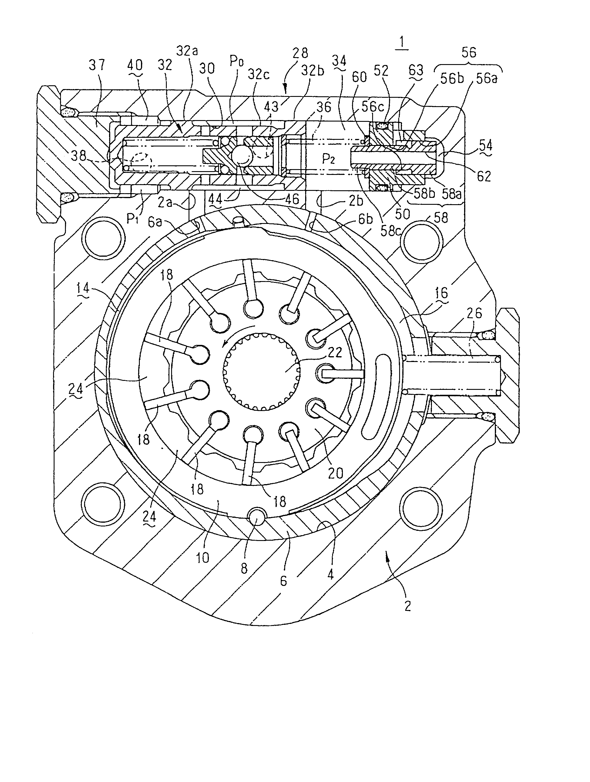
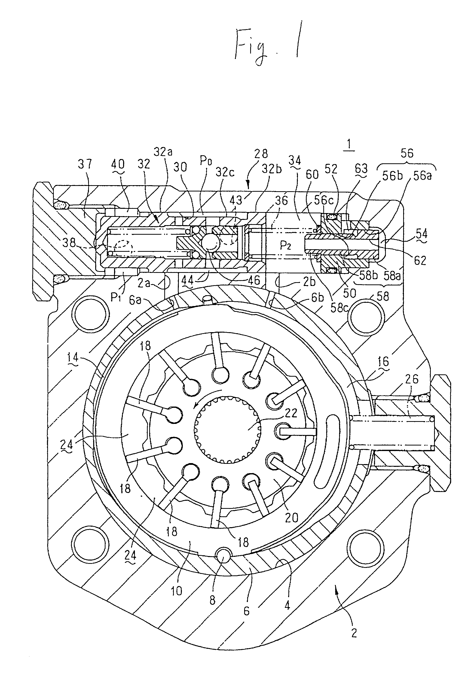
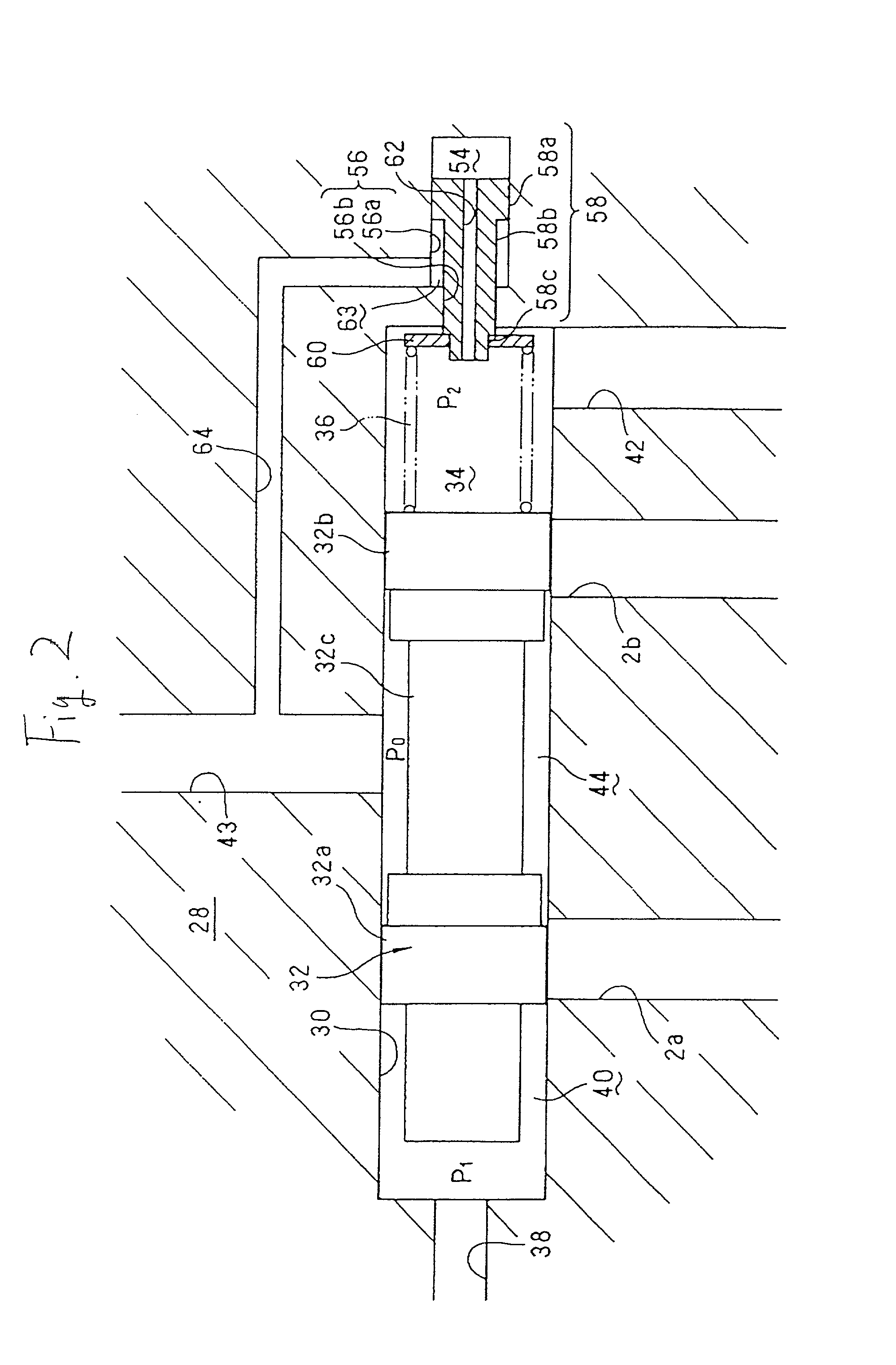
[0052] The outer spring 137 has a low spring constant so that the set load can be less dispersed even when the set length is varied, whereby the dispersion in the flow during the non-steering or in its turn the dispersion in the differential pressure of the metering orifice can be suppressed. Also, the inner spring 136 has such a spring constant that the piston 58 is moved a predetermined displacement when the fluid pressure on the side of the power steering apparatus is increased at the time of steering and reaches a predetermined value. Other constitution is the same as in the

[0053] In this embodiment, the operation is made in the same manner as in the first embodiment, exhibiting the same effect. Moreover, in the first embodiment, the single spring 36 has the function of setting the differential pressure between before and after the metering orifice activating the spool 32, as well as transmitting the thrust of the piston 58 being moved due to working pressure of the power steeri...

fourth embodiment

[0066] In this fourth embodiment, if the vehicle is steered from the equilibrium state (state of FIG. 5) of the spool 32, and the working pressure of the power steering apparatus is increased to move the piston 358 to the left, the thrust is not applied via the springs 36 and 136 as in the above embodiments, but the piston 358 directly presses the spool 32 and moves it to the left in FIG. 5.

[0067] In this fourth embodiment, the operation is performed in the same manner as in the above embodiments, resulting in the same effect. Moreover, the spring 336 biasing the spool 32 has a low spring constant, so that the dispersed flow during the non-steering can be suppressed even when the set length is varied. Also, the piston 358 directly presses the spool 32, but not via the spring 336, the control valve can be switched swiftly and surely at the time of steering, and the discharge flow of the pump increased.

[0068] The present invention is not limited to the above embodiments, but may be mo...


PUM


Abstract

A cam ring 10 is slidably supported within a pump body 2, and a rotor 20 is rotatably disposed inside the cam ring. The cam ring is eccentric to a rotation shaft 22 of the rotor. The rotor carries a plurality of vanes 18 that can be advanced or retreated, in which a pump chamber 24 is formed in a space between the cam ring and the rotor. The cam ring is formed with the first and second fluid pressure chambers 14 and 16 on both sides thereof, and biased in a direction where the displacement of the pump chamber is at maximum by a spring 26. A control valve 28 is provided in which a differential pressure across a metering orifice is applied on both ends of a spool 32 and a spring 36 is disposed on the side of an end face where a downstream fluid pressure is applied. The fluid pressures of the fluid pressure chambers 14 and 16 are controlled by means of the control valve, whereby the cam ring is swung. A piston 58 that is moved in accordance with an increase in working pressure of a power steering apparatus is provided. This piston 58 exerts an axial thrust to an end face of the spool on the spring side.

Description

[0001] 1. Field of the Invention[0002] The present invention relates to a variable displacement pump used in a pressure fluid utilization equipment such as a power steering apparatus for reducing a handle operating force of a vehicle.[0003] 2. Description of the Related Art[0004] For example, a fluid pressure pump for use with a power steering apparatus is required to supply a full amount of pressure fluid to a power cylinder of a power steering apparatus to obtain a steering auxiliary force corresponding to a steering condition, when performing steering operation of a steering wheel (a so-called steering time). On the other hand, during the non-steering such as while the vehicle is running straight, supply of the pressure fluid is practically unnecessary. Also, the pump for the power steering apparatus is required to reduce the amount of supplying the pressure fluid while running at high speed below that at stoppage or while running at low speed, whereby it is desired to offer some...

Claims


Application Information

Patent Timeline
Patent Type & Authority Applications(United States)
IPC IPC(8): B62D5/07F04B49/00F04C2/344F04C14/22F04C14/24
CPCF04C14/226
Inventor KONISHI, HIDEO
Owner UNISIA JKC STEERING SYST
Why Eureka
Try Eureka