Increased shear power for subsea BOP shear rams

a bop shear ram and subsea technology, applied in the direction of sealing/packing, earthwork drilling and mining, borehole/well accessories, etc., can solve the problems of less than full accumulator pressure, increased wall thickness, and increased yield strength

Active Publication Date: 2012-08-16
REEL POWER LICENSING
View PDF6 Cites 37 Cited by
  • Summary
  • Abstract
  • Description
  • Claims
  • Application Information

AI Technical Summary

Benefits of technology

[0021]Another objective of the present invention is to provide a system which will provide full working pressure differential of the operating cylinders to shear the drill pipe even when the accumulator pressure has declined due to partial discharge of the accumulators.
[0022]Another objective of the present invention is to provide a system w

Problems solved by technology

As drill pipe becomes larger in diameter, greater in wall thickness, and higher in yield strength they become more and more difficult to shear.
A further complication to this is that when accumulators are used as the power source to do the shearing, less than full accumulator pressure is available when the accumulators discharge enough fluid to move forward and initiate the shearing action.
The combination of more difficult to shear pipe and less than full pressure to do the shearing has resulted in the fact that some of the pipes cannot be sheared.
It is a low pressure pipe and will control

Method used


Image

  • Increased shear power for subsea BOP shear rams
  • Increased shear power for subsea BOP shear rams
  • Increased shear power for subsea BOP shear rams

Examples


Embodiment Construction

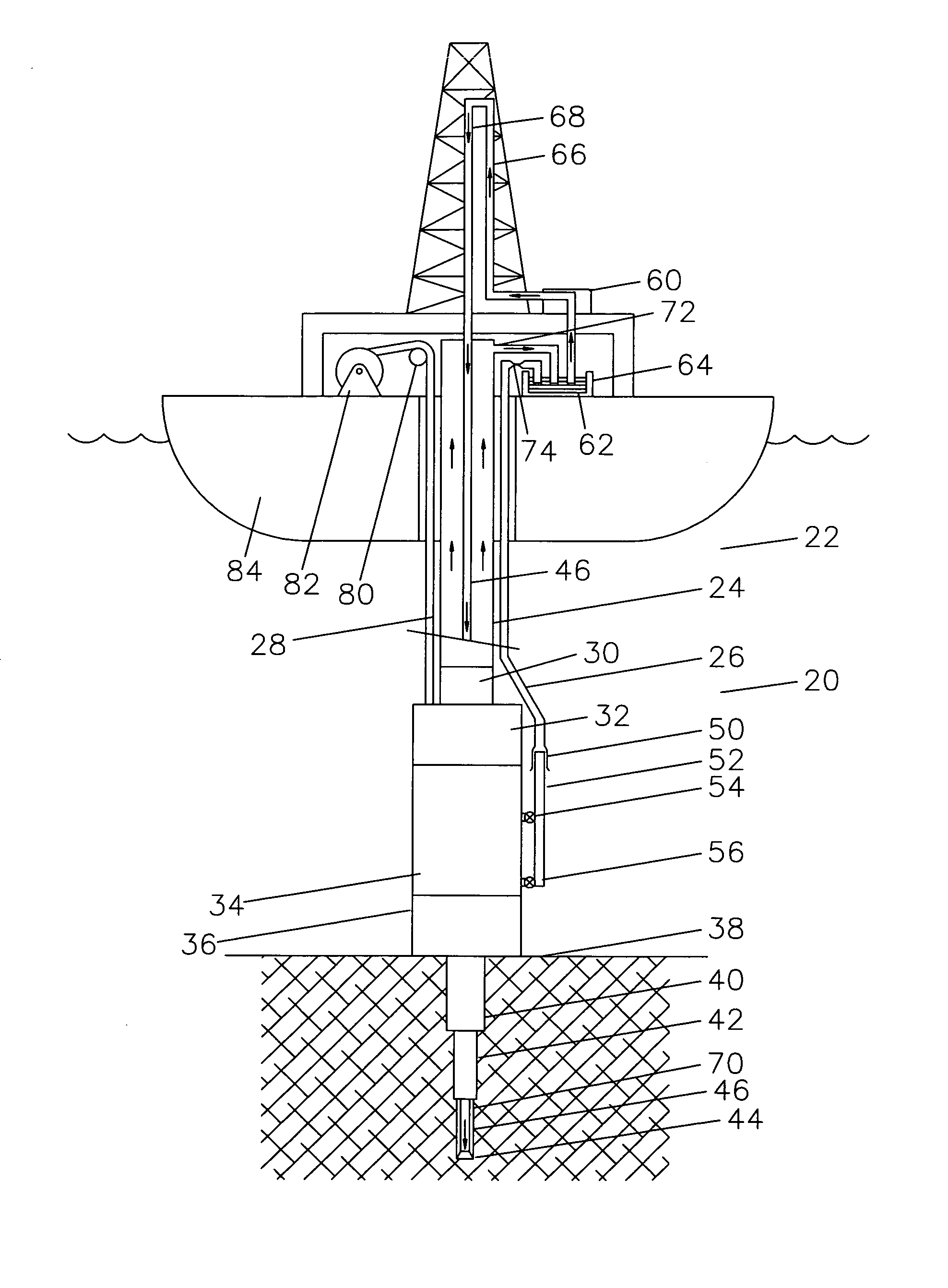
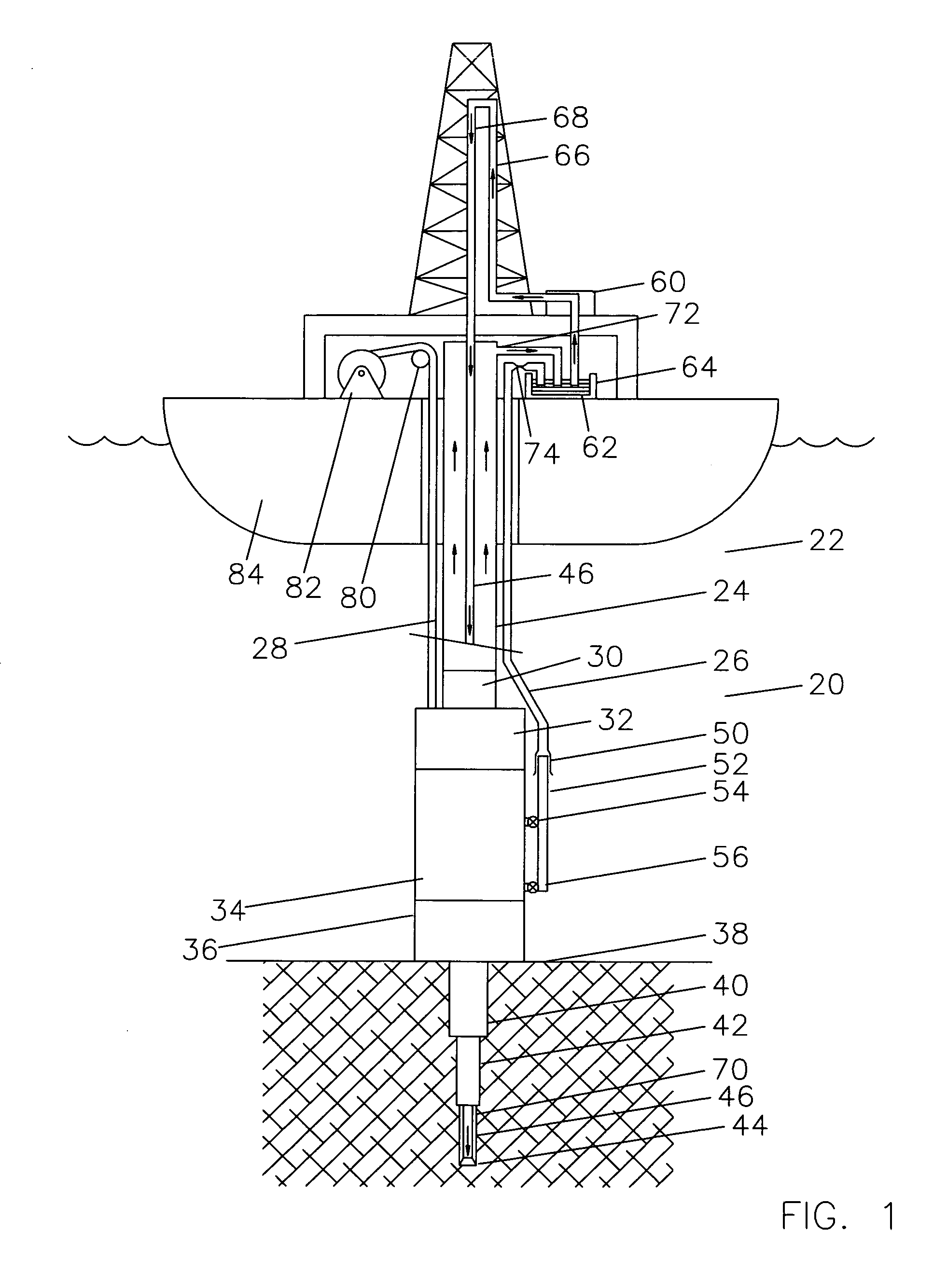
[0028]Referring now to FIG. 1, a view of a complete system for drilling subsea wells 20 is shown in order to illustrate the utility of the present invention. The drilling riser 22 is shown with a central pipe 24, outside fluid lines 26, and cables or hoses 28.

[0029]Below the drilling riser 22 is a flex joint 30, lower marine riser package 32, lower blowout preventer stack 34 and wellhead 36 landed on the seafloor 38.

[0030]Below the wellhead 36, it can be seen that a hole was drilled for a first casing string, that string 40 was landed and cemented in place, a hole drilled through the first string for a second string, the second string 42 cemented in place, and a hole is being drilled for a third casing string by drill bit 44 on drill string 46.

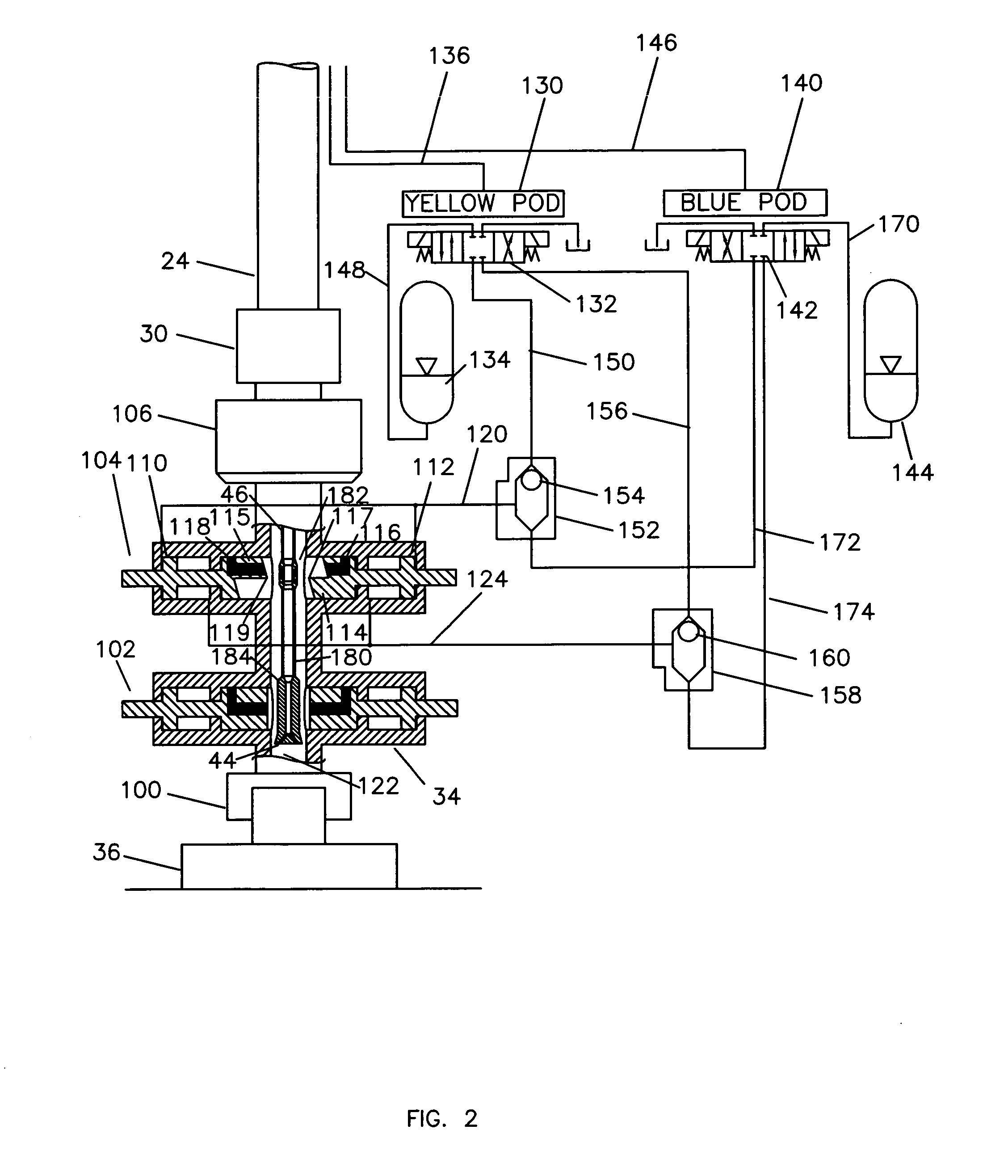
[0031]The lower Blowout Preventer stack 34 generally comprises a lower hydraulic connector for connecting to the subsea wellhead system 36, usually 4 or 5 ram style Blowout Preventers, an annular preventer, and an upper mandrel for connection ...


PUM


Abstract

The method of providing a desired motive force for one or more rams of a subsea blowout preventer as a function of a desired pressure differential across one or more pistons on the subsea blowout preventer when the desired pressure differential is higher than the gauge pressure of the accumulators supplying the pressure, comprising providing one or more pistons connected to the one or more rams, the pistons having a distal side and a proximate side with respect to the rams, providing a first pressure from the accumulators to the distal side of the pistons, providing a tank to contain a second pressure less than the ambient pressure of seawater at the location of the subsea blowout preventer, providing a pressure reducing valve which exhausts into the tank and reduces the pressure on the proximate side of the one or more pistons to proximately the difference between the desired pressure differential and the first pressure further comprising that the pressure differential across the one or more pistons is proximately equal to the maximum working pressure of the one or more cylinders plus an amount to provide a force towards the bore of the blowout preventer stack to offset the force of the pressure in the bore acting on the exposed end of rods of the one or more piston.

Description

TECHNICAL FIELD[0001]This invention relates to the general subject connecting a low or negative pressure accumulator to the low pressure side of the pistons operating blowout preventer rams in a high pressure subsea environment to increase the shearing force in a controlled fashion.CROSS-REFERENCE TO RELATED APPLICATIONS[0002]Not applicable.STATEMENT REGARDING FEDERALLY SPONSORED RESEARCH OR DEVELOPMENT[0003]Not applicableREFERENCE TO A “MICROFICHE APPENDIX”[0004]Not applicableBACKGROUND OF THE INVENTION[0005]The field of this invention is that of operating blowout preventers in deep water operations to shear pipe within the well bore and to seal the well bore to protect the environment in emergency situations when an obstruction is in the well bore.[0006]Shear rams in blowout preventers are designed to cut the pipe in emergency situations and allow the bore to be closed and secure the well against unintended discharges of oil or gas to the environment. Blind shear rams are designed...

Claims


Application Information

Patent Timeline
IPC IPC(8): E21B33/06
CPCE21B33/063E21B34/04E21B33/064
Inventor BAUGH, BEMTOM FREDERICK
Owner REEL POWER LICENSING
Why Eureka
Try Eureka