
Vertical cavity surface emitting laser device

a laser device and vertical cavity technology, applied in the direction of laser details, optical resonator shape and construction, semiconductor lasers, etc., can solve the problems of thermal saturation characteristic of the optical output power of the conventional vcsel device having a wavelength of 850 nanometers (nm), the maximum optical output power of the conventional vcsel device is saturated and the optical output power is lower than the desired optical output power

Inactive Publication Date: 2002-08-01
FURUKAWA ELECTRIC CO LTD
View PDF0 Cites 41 Cited by
  • Summary
  • Abstract
  • Description
  • Claims
  • Application Information

AI Technical Summary

Problems solved by technology

It is known that a VCSEL device formed on an n-type substrate has a disadvantage compared to a VCSEL device formed on a p-type substrate.
Nevertheless, there is a problem in that the thermal saturation characteristic of the optical output power in the conventional VCSEL device having a wavelength of 850 nanometers (nm) is not satisfactory.
More specifically, in a high ambient temperature, the maximum optical output power of the VCSEL device is saturated and lower than the desired optical output power.

Method used


Image

  • Vertical cavity surface emitting laser device
  • Vertical cavity surface emitting laser device
  • Vertical cavity surface emitting laser device

Examples


second example

[0073] Another sample of the VCSEL device of the present embodiment possessing high thermally conductivity and having an effective emission area of about 300 .mu.m.sup.2 was fabricated. A comparative example based on the conventional design was also fabricated. This conventional design had a structure similar to the structure of the high thermal conductive sample with some significant differences, such as in the lower layer structure, e.g., the comparative example did not have an AlAs layer as a lower-refractive index layer.

[0074] The relationship between the optical output power and the injected current is investigated in both the high thermally conductive sample and the comparative example, with the operational temperature thereof being varied. The results shown in FIG. 11 were obtained to demonstrate the temperature dependency of the output power-injected current characteristic.

[0075] As understood from the comparison of FIG. 11 and FIG. 3, although a difference is not observed b...


PUM


Abstract

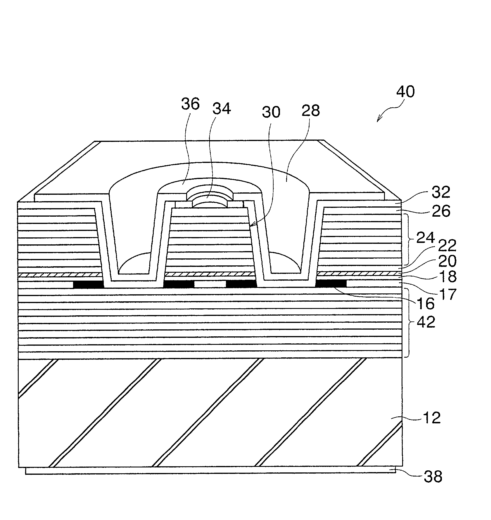
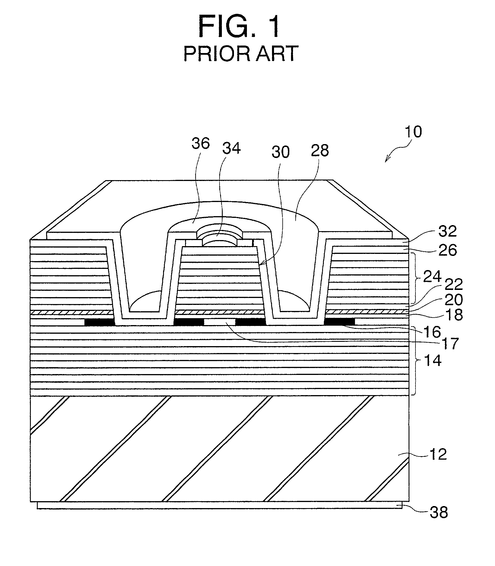
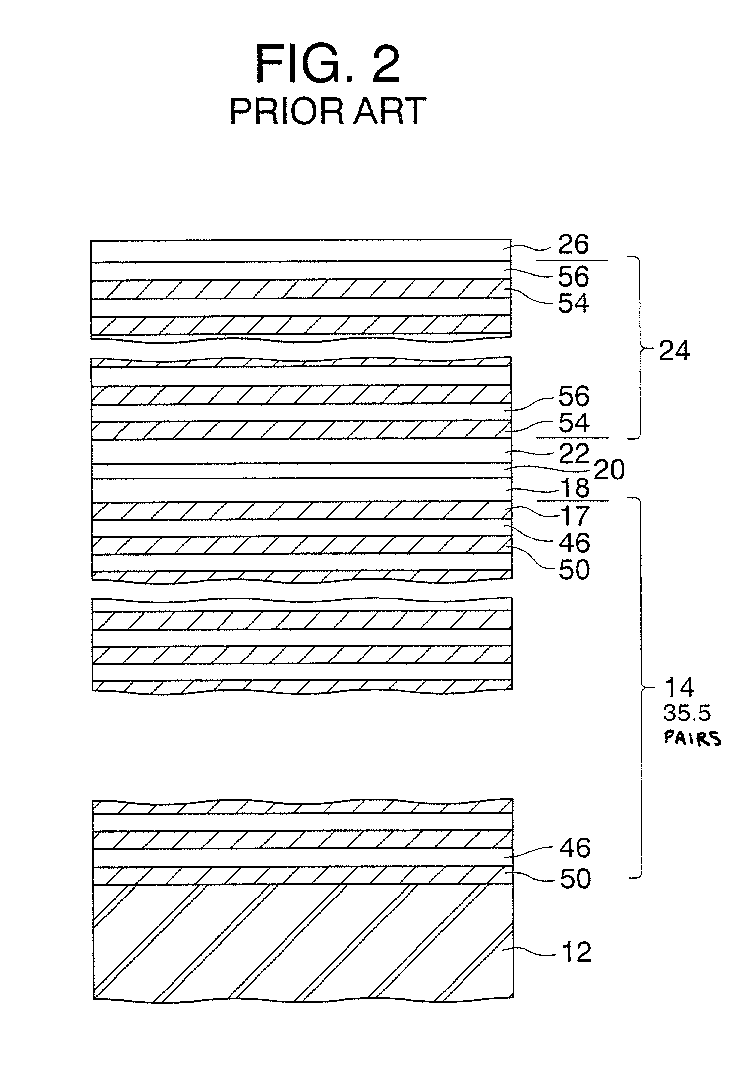
A vertical cavity surface emitting laser (VCSEL) device includes a pair of diffusion Bragg reflectors (DBRs) sandwiching therebetween a multiple quantum well (MQW) comprising active layers. The bottom DBR includes a lower layer structure having AlAs layers having a higher thermal conductivity and AlGaAs layers in pair and an upper layer structure acting anti-oxidation layers and having a pair of AlGaAs layers having different Al contents. A selectively oxidized AlAs layer disposed as the top layer of the bottom DBR comprises an Al-oxidized area and a non-oxidized layer for confinement of current injection path.

Description

[0001] 1. Field of the Invention[0002] The present invention relates to a vertical cavity surface emitting laser device (VCSEL).[0003] 2. Description of the Related Art[0004] The vertical cavity surface emitting laser (VCSEL) device emits laser light in the direction normal to the substrate surface, and has an advantage in that a large number of such laser devices can be integrated to form a two-dimensional array on a single substrate. Thus, the VCSEL device is expected for use in a parallel optical information processing and large-capacity parallel optical transmission.[0005] Among other VCSEL devices, a GaAs-based VCSEL device having distributed Bragg reflectors (DBRs) attracts large attention as a light source for optical communication equipment for use in the field of data communication. The GaAs-based VCSEL device includes a GaAs substrate, a pair of DBRs overlying the GaAs substrate and including a plurality of pairs of AlGaAs / AlGaAs layers having different Al contents, and at...

Claims


Application Information

Patent Timeline
Patent Type & Authority Applications(United States)
IPC IPC(8): H01S5/183H01L21/205
CPCH01S5/02461H01S5/18313
Inventor YOKOUCHI, NORIYUKITACHIBANA, MASATOUEDA, NATSUMISHINAGAWA, TATSUYUKI
Owner FURUKAWA ELECTRIC CO LTD
Features
  • Generate Ideas
  • Intellectual Property
  • Life Sciences
  • Materials
  • Tech Scout
  • Unparalleled Data Quality
  • Higher Quality Content
  • 60% Fewer Hallucinations
Learn More