Method and apparatus for cancellation of borehole effects due to a tilted or transverse magnetic dipole

Inactive Publication Date: 2002-08-08
SCHLUMBERGER TECH CORP
View PDF0 Cites 46 Cited by
  • Summary
  • Abstract
  • Description
  • Claims
  • Application Information

AI Technical Summary

Benefits of technology

0022] Another embodiment of the invention provides a method for correcting for the effect of an axial electric current flow along a subsurface borehole in the vicinity of a receiver antenna disposed within the borehole, the receiver antenna being disposed such that the magnetic dipole moment of the antenna is tilted or perpendicular with respect to the borehole axis, the axial current being associated with electromagnetic energy transmitted from a transmitter antenna disposed within the borehole. The method comprises disposing a first pair of electrodes within the borehole such that the antenna is located between the electrodes, the first electrode pair being adapted for joint electromagnetic interaction; disposing a second pair of electrodes within the borehole such that the first electrode pair is located between the second electrode pair, the second electrode pair being adapted for joint electromagnetic interaction; measuring a voltage signal associa

Problems solved by technology

A particularly troublesome property of the TMD is the extremely large borehole effect that occurs in high contrast situations, i.e., when the mud in the borehole is much more conductive than the formation.
When these currents pass by TMD re

Method used


Image

  • Method and apparatus for cancellation of borehole effects due to a tilted or transverse magnetic dipole
  • Method and apparatus for cancellation of borehole effects due to a tilted or transverse magnetic dipole
  • Method and apparatus for cancellation of borehole effects due to a tilted or transverse magnetic dipole

Examples


Embodiment Construction

[0036] Before proceeding with disclosure of the invention, some theoretical consideration shall be set forth.

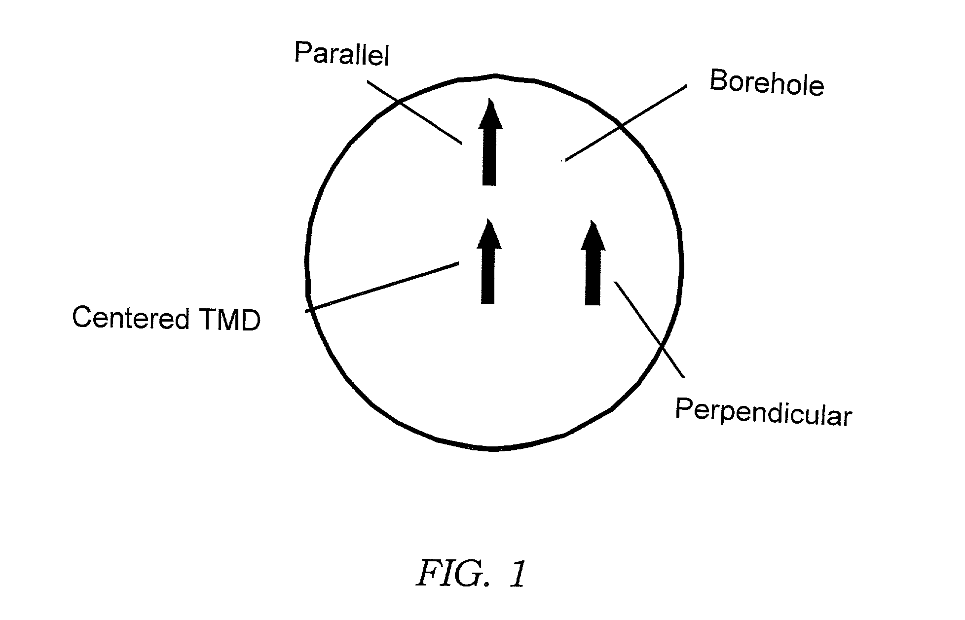
[0037] A TMD can be eccentered in a borehole in two possible orientations, which we will call parallel and perpendicular eccentering as shown in FIG. 1. Parallel eccentering forces currents symmetrically up and down the borehole and therefore no net current is generated. This borehole effect is no worse than in a typical downhole instrument equipped with non-tilted (axial) antennas. Perpendicular eccentering gives rise to a large axial borehole current in the case of an insulated instrument body, which strongly couples to a transverse receiver an axial distance away (not shown). These two displacements are the extremes of the possible ones. In the general case, the eccentering will be in a direction that is at some angle to the dipole moment of the sensors. In this case, the borehole effect lies between the two extreme cases.

[0038] It is important to understand the basic diff...


PUM


Abstract

Methods and apparatus are disclosed for minimizing or eliminating an undesired axial electric current induced along a subsurface borehole in the process of subsurface measurements with transmitter and/or receiver antennas which are substantially time varying magnetic dipoles with their dipole moments aligned at an angle to the axis of the borehole. Some antennas are disposed within the borehole on instruments having a non-conductive support member. One instrument includes a conductive all-metal body with an antenna adapted for induction frequencies. Antenna shields adapted for controlled current flow are also provided with an all-metal instrument. Methods include providing an alternate path for the current along the instrument body. Another method includes emitting a controlled current to counter the undesired current. Another method corrects for the effect of the current using a superposition technique. An embodiment of the instrument includes an antenna disposed between a pair of electrically coupled electrodes. The antenna is disposed on the instrument such that it comprises a tilted or transverse magnetic dipole. Another embodiment of the instrument includes a non-conductive housing with a conductive segment disposed thereon. An antenna is disposed on the instrument about the conductive segment. Another embodiment includes an antenna disposed between two pairs of electrodes with means to measure a voltage at the electrodes when electromagnetic energy is transmitted within the borehole. Yet another instrument includes an antenna disposed between a first pair of electrodes and means to measure a voltage at the electrodes when electromagnetic energy is transmitted within the borehole. This embodiment also includes means to energize a second electrode pair in response to the voltage measured at the first electrode pair.

Description

1. BACKGROUND OF THE INVENTION[0001] 1.1 Field of the Invention[0002] The invention relates to techniques for reducing and / or correcting for borehole effects encountered in subsurface measurements. More particularly, the invention concerns methods, and devices for their implementation, in which well logging instruments using sources or sensors having a transverse or tilted magnetic dipole are adapted to reduce or correct for undesired electromagnetic effects associated with the deployment of the instruments in a borehole.[0003] 1.2 Description of Related Art[0004] Various well logging techniques are known in the field of hydrocarbon exploration and production. These techniques typically employ logging instruments or "sondes" equipped with sources adapted to emit energy through a borehole traversing the subsurface formation. The emitted energy interacts with the surrounding formation to produce signals that are detected and measured by one or more sensors on the instrument. By proces...

Claims


Application Information

Patent Timeline
IPC IPC(8): G01V3/28
CPCG01V3/28
Inventor ROSTHAL, RICHARD A.HOMAN, DEANBARBER, THOMAS D.BONNER, STEPHENCLARK, BRIANOMERAGIC, DZEVAT
Owner SCHLUMBERGER TECH CORP
Why Eureka
Try Eureka