Figure-8 optical fiber pulse laser using a dispersion imbalanced nonlinear optical loop mirror

a optical fiber pulse technology, applied in the field of figure8 optical fiber pulse laser using a dispersion imbalanced nonlinear optical loop mirror, can solve the problems of difficult to produce stable pulse trains

Inactive Publication Date: 2002-08-08
GWANGJU INST OF SCI & TECH
View PDF0 Cites 18 Cited by
  • Summary
  • Abstract
  • Description
  • Claims
  • Application Information

AI Technical Summary

Problems solved by technology

It may produce a femto-second optical pulse train, but it has a difficulty to produce stable pulse trains.
However, it is difficult to produce the stable pulse train due to the noise and the stimulated Brillouin scattering.

Method used


Image

  • Figure-8 optical fiber pulse laser using a dispersion imbalanced nonlinear optical loop mirror
  • Figure-8 optical fiber pulse laser using a dispersion imbalanced nonlinear optical loop mirror
  • Figure-8 optical fiber pulse laser using a dispersion imbalanced nonlinear optical loop mirror

Examples


first embodiment

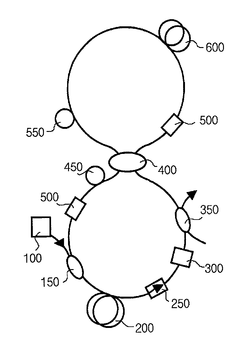
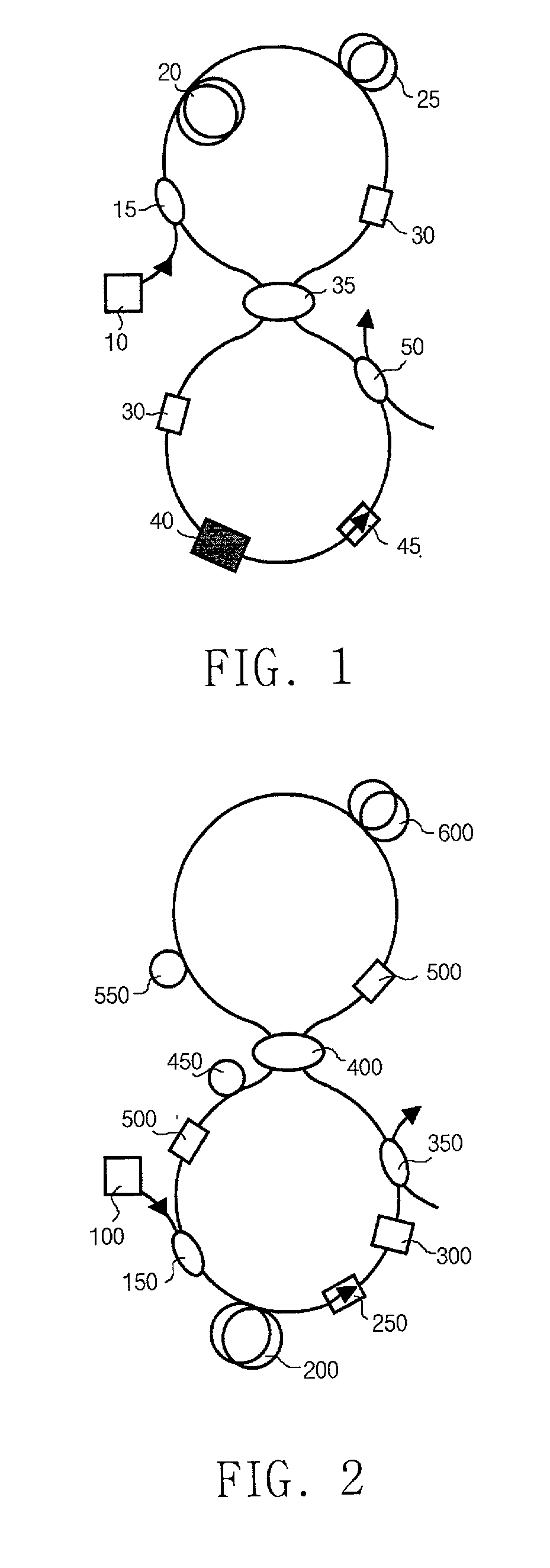
[0028] FIG. 2 shows a schematic diagram for an optical fiber laser according to the present invention. The dispersion values are unbalanced at the nonlinear optical loop mirror, and the stable switching is accomplished. The linear loop part comprises a pump LD (100), a WDM coupler (150), an EDF (200), an isolator (250), a BPF (300), an output coupler (350), a DCF (dispersion compensated fiber) (450), and a PC (500). On the other hand, the nonlinear loop part comprises a SMF (single mode fiber) (550), a DSF (600), and a PC (500). An optical coupler (400) combines the linear part and the nonlinear part as shown in FIG. 2.

[0029] EDF (200) is used as an amplifier in the linear part of the figure-8 optical fiber. Where, the optical pulses are propagating through the EDF (200) unidirectionally using the optical isolator (250). And the several unstable phenomena due to the bidirectional propagation through EDF (200) are removed.

[0030] In addition, DI-NOLM is used for the switching role in ...

second embodiment

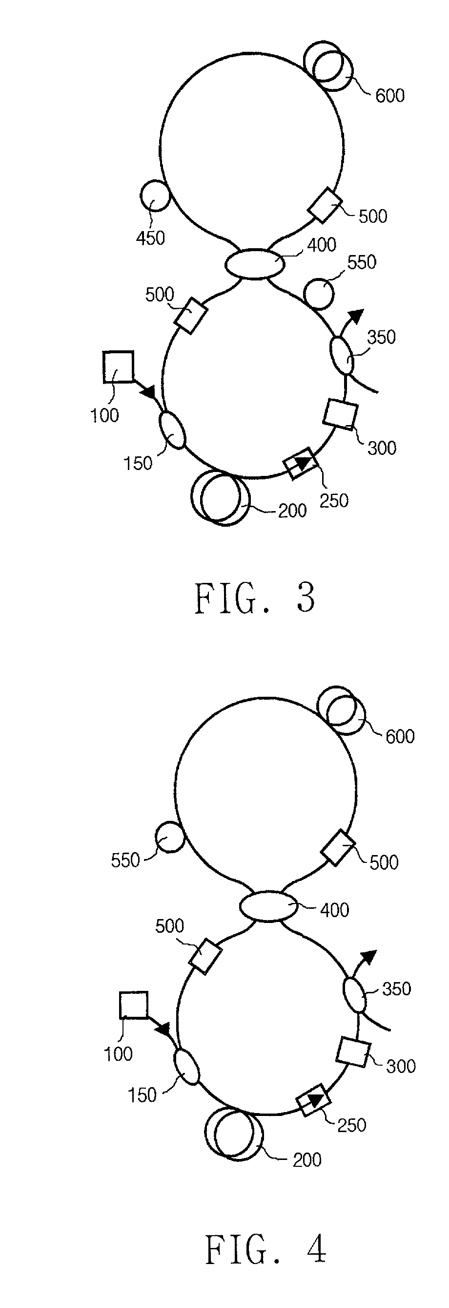
[0031] FIG. 3 shows a schematic diagram for an optical fiber laser according to the present invention. The linear loop part comprises a pump LD (100), a WDM coupler (150), an EDF (200), an optical isolator (250), a BPF (300), an output coupler (350), a SMF (550), and a PC (500), while the nonlinear loop part comprises a DCF (450), a DSF (600), and a PC (500). An optical coupler (400) combines the linear part and the nonlinear part as shown in FIG. 3.

[0032] The second embodiment in FIG. 3 is similar to the first one in FIG. 2; SMF (550) is interchanged with DCF (450). The optical pulses are chirped through SMF (550) at the lower loop of the figure-8 laser. The optical pulses are divided into two at the 3-dB optical coupler (400). One of them propagates the loop clockwise, while, the other propagates the loop counterclockwise. The clockwise pulses become narrower at DCF (450), and then pass DSF (600). On the other hand, the counterclockwise pluses pass DSF (600) first, and then, becom...

third embodiment

[0033] FIG. 4 shows a schematic diagram for an optical fiber laser according to the present invention. The linear loop part comprises a pump LD (100), a WDM coupler (150), an EDF (200), an optical isolator (250), a BPF (300), an output coupler (350), and a PC (500), while the nonlinear loop part comprises a SMF (550), a DSF (600), and a PC (500). An optical coupler (400) combines the linear part and the nonlinear part as shown in FIG. 4.

[0034] The third embodiment in FIG. 4 is similar to the first one in FIG. 2; DCF (450) is eliminated at the lower loop of the figure-8 laser. Only the chirped optical pulses propagate through DI-NOLM by acquiring the self-switching effect due to the functional principles. And, when the optical pulses are amplified at EDF (200), only the self-chirped pulses survive to pass through DI-NOLM, and return to EDF (200). Therefore, the figure-8 optical fiber laser produces narrow optical pulses.

[0035] FIG. 5 shows a schematic diagram for an optical fiber las...


PUM


Abstract

The present invention relates to a figure-8 optical fiber pulse laser using a dispersion imbalanced nonlinear optical loop mirror (DI-NOLM). The conventional figure-8 optical fiber pulse laser uses a nonlinear optical fiber mirror having an EDF as a gain material. The conventional laser has an advantage for the simple structure, and it can be easily constructed. However, it can not produce the stable optical pulse trains. The figure-8 optical fiber pulse laser according to the present invention produces stable femto-second optical pulses using DI-NOLM. The optical amplifier is not included in DI-NOLM, instead, it is located at the unidirectional linear loop part. And the noise due to the bidirectional gain difference of the optical amplifier is reduced. Two optical fibers of different dispersion values are used at DI-NOLM. Therefore, the present invention provides a figure-8 optical fiber pulse laser using DI-NOLM improving the switching characteristic. Especially, the stable femto-second laser according to the present invention is applicable for the many applications such as high-speed reaction measurements, laser treatments, and medical lasers.

Description

[0001] 1. Field of the Invention[0002] The present invention relates generally to a figure-8 optical fiber pulse laser using a dispersion imbalanced nonlinear optical loop mirror (DI-NOLM). More particularly, it relates to a new type of the figure-8 optical fiber pulse laser generating stable femto-second optical pulse trains.[0003] 2. Description of the Related Art[0004] Generally, the mode-lock method of this laser is a skill to produce a pulse train of narrow pulse width using a laser, and it is divided into the active mode-lock method and the passive one. The conventional figure-8 optical fiber laser is one of the passively mode-locked optical fiber lasers. It may produce a femto-second optical pulse train, but it has a difficulty to produce stable pulse trains. In order to improve the switching effect of a nonlinear optical loop mirror (NOLM) as a switch of the figure-8 optical fiber laser, an optical amplifier is added into the NOLM to form a nonlinear amplifying loop mirror (...

Claims


Application Information

Patent Timeline
Patent Type & Authority Applications(United States)
IPC IPC(8): H01S3/067H01S3/098
CPCH01S3/06791H01S3/082H01S3/1112H01S3/067
Inventor KIM, DUCK YOUNGSUNG, NAK HYOUN
Owner GWANGJU INST OF SCI & TECH
Why Eureka
Try Eureka