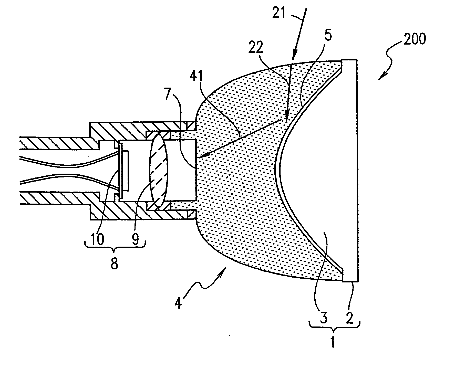
Imaging device and method for producing the same
a technology which is applied in the field of imaging device and camera for producing the same, can solve the problems of limited viewing angle, is not suitable for such applications, and noise to the light incident on the convex rotational mirror or the noise to the light reflected by the convex rotational mirror is not generated
- Summary
- Abstract
- Description
- Claims
- Application Information
AI Technical Summary
Benefits of technology
Problems solved by technology
Method used
Image
Examples
example 2
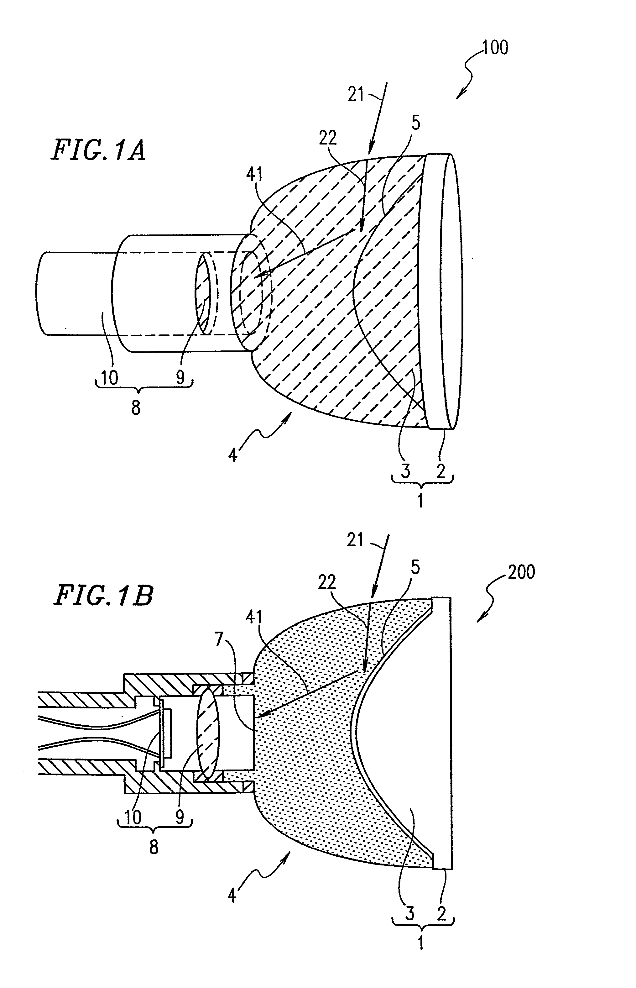
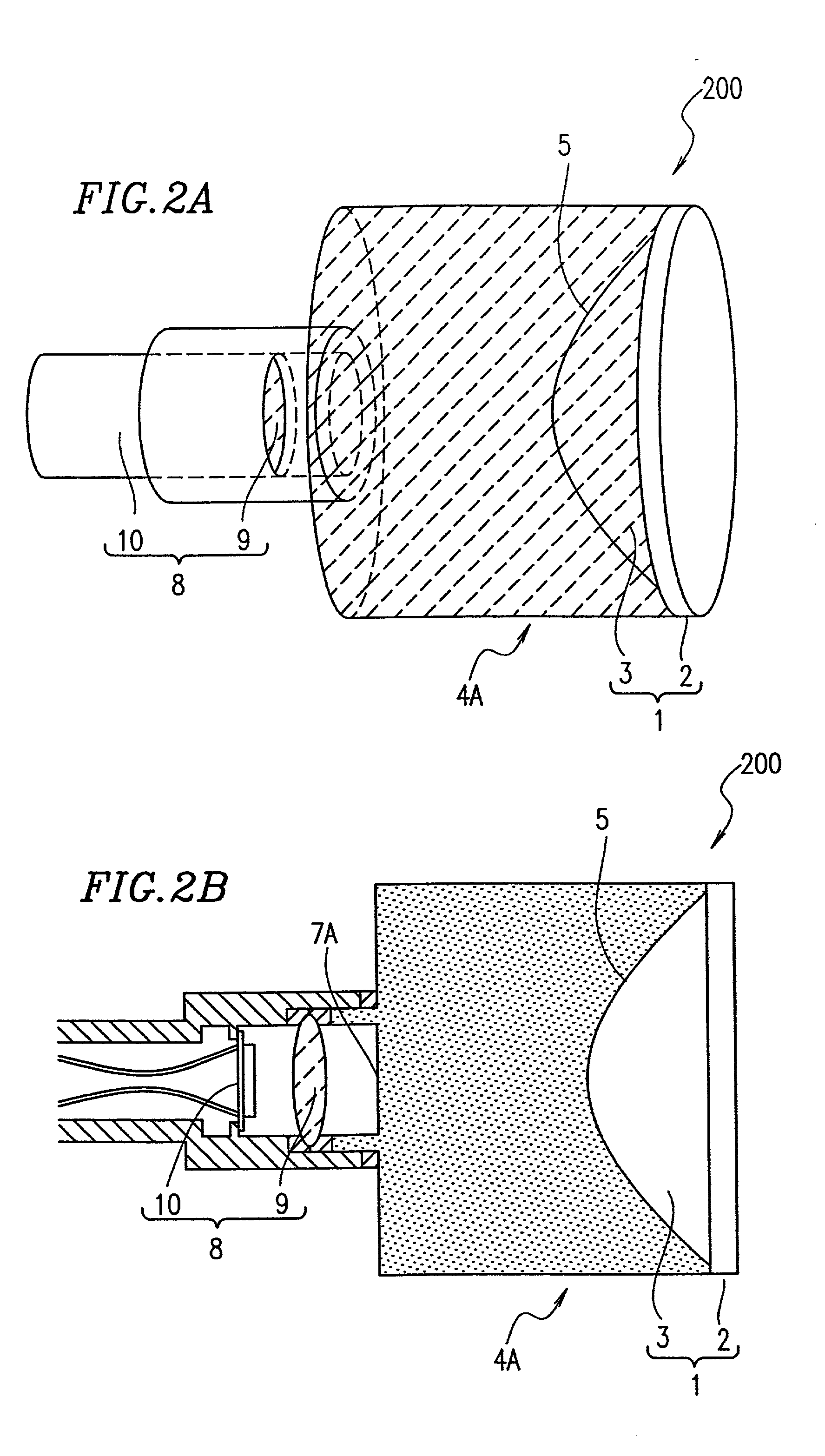
[0073] FIG. 4A shows a schematic structure of an imaging device 400 according to a second example of the present invention, and FIG. 4B is a cross-sectional view thereof taken along a plane including the rotation axis of a convex rotational mirror 3. Identical elements described above referring to FIGS. 1A and 1B bear identical reference numerals therewith and detailed descriptions thereof will be omitted.
[0074] An imaging device 400 includes an optical member 4C. The optical member 4C has a reflected light releasing face 7C on the opposite side to the convex rotational mirror unit 1. The reflected light releasing face 7C has a curved surface which projects toward the convex rotational mirror 3. The optical member 4C is formed of a light-transmissive material.
[0075] A generally cylindrical imaging mechanism 8C is provided on the opposite side to the convex rotational mirror unit 1 with the optical member 4C interposed therebetween. The imaging mechanism 8C covers the reflected light...
example 3
[0081] FIGS. 5 and 6 show a schematic structure of an imaging device 500 according to a third example of the present invention. Identical elements described above referring to FIGS. 1A and 1B bear identical reference numerals therewith and detailed descriptions thereof will be omitted. The imaging device 500 is different from the imaging device 100 (FIGS. 1A and 1B) in that the imaging device 500 includes an optical member 4D instead of the optical member 4.
[0082] The optical member 4D has an outer circumferential surface formed so as to cause light to be incident thereon in a direction normal thereto (FIG. 5). The optical member 4D includes a reflected light releasing face 7D formed so as to cause the light reflected by the convex rotational mirror 3 to pass therethrough in a direction normal thereto (FIG. 6).
[0083] The imaging device 500, having the above-described structure, operates as follows.
[0084] Light 23, incident on the outer circumferential surface of the optical member 4...
PUM
 Abstract
Description
Claims
Application Information
 - R&D
- Intellectual Property
- Life Sciences
- Materials
- Tech Scout
- Unparalleled Data Quality
- Higher Quality Content
- 60% Fewer Hallucinations
Browse by: Latest US Patents, China's latest patents, Technical Efficacy Thesaurus, Application Domain, Technology Topic, Popular Technical Reports.
© 2025 PatSnap. All rights reserved.Legal|Privacy policy|Modern Slavery Act Transparency Statement|Sitemap|About US| Contact US: help@patsnap.com


