Minute particle optical manipulation method and apparatus

a technology of optical manipulation and minute particles, applied in the field of minute particle optical manipulation and minute particle optical manipulation apparatus, can solve the problems of high cost, damage or destruction of minute living samples, and difficulty in optics to actualize converged beams having a numerical aperture of 1.5

Inactive Publication Date: 2002-08-15
NIKON CORP
View PDF0 Cites 19 Cited by
  • Summary
  • Abstract
  • Description
  • Claims
  • Application Information

AI Technical Summary

Problems solved by technology

In fact, however, it is difficult in terms of optics to actualize the converged beam having a numerical aperture of 1.5 or larger (NA=1.5 or above).
Further, there is also a method of strengthening the light intensity with which the minute particle is irradiated, however, if a large output light source is used, there might be a possibility in which a minute living sample is damaged or destructed.
As a result, each of the laser trapping apparatuses related to the proposals given above involves the use of an expensive prism element and therefore costs high.
Another problem is that this laser trapping apparatus needs a mechanism for accurately holding the prism, which leads a scale-up of the apparatus.
Moreover, the trapping force in the optical-axis direction is enhanced because of using the conical cylindrical converged beam, however, a range where the trapping force acts in the optical-axis direction shrinks, resulting in a problem that only the sample in close proximity to the converging point can be trapped.
Further, generally the optical tweezers have a comparatively weak trapping force in the optical-axis direction, and besides the range where the trapping force acts in the optical-axis direction is limited.
In fact, however, there arises a problem in which even when making the focusing adjustment, the maximum trapping force obtained by the optical tweezers decreases as the position of the minute particle in the medium gets deeper, resulting in a difficulty of trapping the minute particle.
This is because a distance at which the beam travels through the medium surrounding the minute particle becomes longer as the position of the minute particle in the medium gets deeper, with the result that a minus spherical aberration occurs in the converged beam.
Therefore, the maximum trapping force obtained by the optical tweezers becomes weaker as the position of the minute particle in the medium gets deeper, and it is difficult to trap the minute particle.
Further, if the minute particle exists deep inside the medium under the cover glass, a minus spherical aberration occurs when the converged beam travels through the medium in the prior art.
On the other hand, above the upper limit of the condition (1), the trapping force of the minute particle can not be stably maintained strong undesirably since the absolute value of the axial chromatic aberration .DELTA. is too small so that the plus spherical aberration can not be given to the converged beam sufficiently.

Method used


Image

  • Minute particle optical manipulation method and apparatus
  • Minute particle optical manipulation method and apparatus
  • Minute particle optical manipulation method and apparatus

Examples


second example

[0126] FIG. 7 is a view showing a whole configuration of the minute particle optical manipulation apparatus in a second example of the present invention. Note that the same components as those of the minute particle optical manipulation apparatus illustrated in FIG. 6, are marked with the like numerals, and their repetitive explanations are omitted.

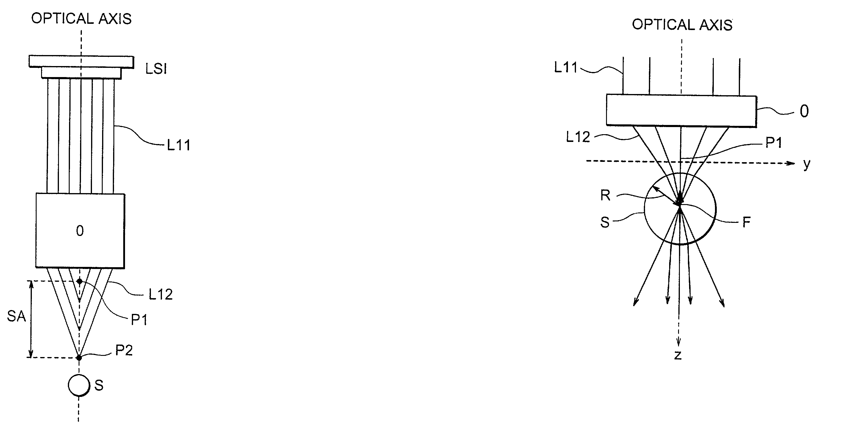
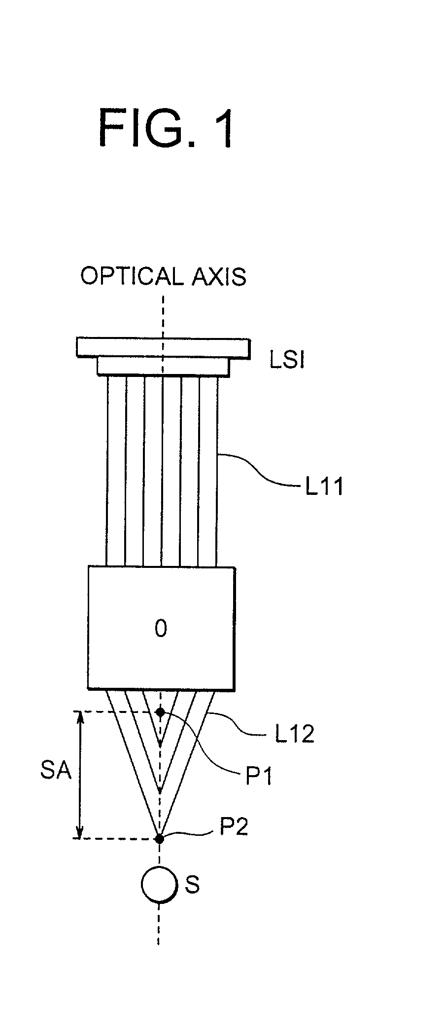
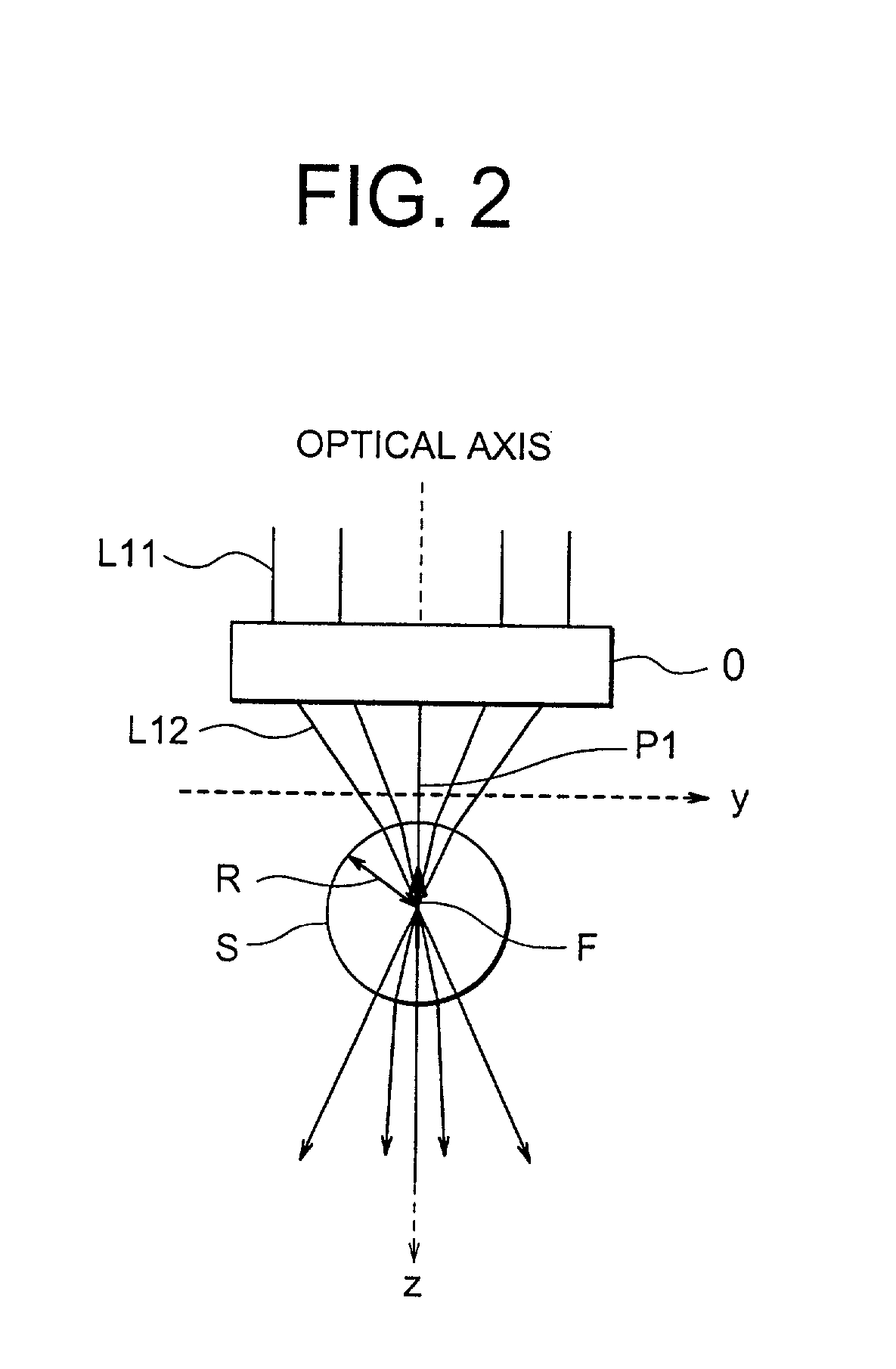
[0127] As shown in FIG. 7, in the minute particle optical manipulation apparatus in the second example, there are disposed the optical tweezers oriented light source LS1 for emitting the beam for optical tweezers, the dichroic mirror DM for reflecting downwards the beam from the optical tweezers oriented light source LS1, and a converging optical system O for converging the beam emerging from the dichroic mirror DM in a way that gives the predetermined plus spherical aberration SA thereto, i.e., the converging optical system O, shown in FIGS. 1 and 2, for giving the plus spherical aberration SA.

[0128] The minute particle optical manipulat...

third example

[0140] FIG. 8 is a view showing a whole configuration of the minute particle optical manipulation apparatus in a third example of the present invention. Note that the same components as those of the minute particle optical manipulation apparatus illustrated in FIG. 7, are marked with the like numerals, and their repetitive explanations are omitted.

[0141] As shown in FIG. 8, in the minute particle optical manipulation apparatus in the third example, there are disposed the optical tweezers oriented light source LS1 for emitting the beam for optical tweezers, and the converging optical system O for converging the parallel beam L11 emitted from the optical tweezers oriented light source LS1 in a way that gives the predetermined plus spherical aberration SA thereto, i.e., the converging optical system O, shown in FIGS. 1 and 2, for giving the plus spherical aberration SA.

[0142] The minute particle optical manipulation apparatus in the third example takes, as compared with the conventiona...

fourth example

[0153] A fourth example will be explained referring to FIG. 9. FIG. 9 shows a configuration in which an electric revolver RV, a control unit C and an input device I are added so that the minute particle can be observed while switching a plurality of objective lenses OL.sub.1, OL.sub.2, OL.sub.3 each having a different magnification, and the operations of the turret T and the revolver RV are automated. The same members as those in the examples discussed above are marked with the like numerals, and their repetitive explanations are omitted. The turret T and the revolver RV are fitted with rotary motors (not shown), and the rotations thereof are controlled by signals transmitted from the control unit C. The input device I including, e.g., a switch, a keyboard etc. is connected to the control unit C. The user is able to switch over a magnification of the objective lens to a desired magnification by operating this input device I. At this time, the control unit C transmits the signal for ...


PUM


Abstract

A minute particle optical manipulation method and a minute particle optical manipulation apparatus are capable of simply strengthening a trapping force in an optical-axis direction and expanding a range where the trapping for acts in the optical-axis direction without requiring an optical element such as a special prism etc., and obtaining the trapping force enough to trap the particle even when the minute particle exists deep within a medium while keeping the trapping force when the minute particle is in a shallow position within the medium.

Description

[0001] This application claims the benefit of Japanese Applications No. 2000-105968 and No. 2001-109394, which are hereby incorporated by reference.[0002] 1. Field of the Invention[0003] The present invention relates generally to a minute particle optical manipulation method and a minute particle optical manipulation apparatus, and more particularly to a minute particle optical manipulation method and a minute particle optical manipulation apparatus for three-dimensionally trapping and moving a minute particle by irradiating the minute particle with beams.[0004] 2. Related Background Art[0005] A technology of optically manipulating a minute particle is generally known as optical tweezers and optical trapping. This technology involves the use of mainly a laser and is therefore called laser trapping and laser tweezers.[0006] This technology is that laser beam emitted from a radiation source is converged in a conical shape by a converging optical system and falls upon the vicinity of t...

Claims


Application Information

Patent Timeline
Patent Type & Authority Applications(United States)
IPC IPC(8): G21K1/00H05H3/04
CPCG21K1/006H05H3/04
Inventor MATSUI, KUMIKOOKUGAWA, HISASHI
Owner NIKON CORP
Why Eureka
Try Eureka