Optical device
a technology of optical devices and optical waveguides, applied in the direction of optical waveguide light guides, instruments, nanotechnology, etc., can solve the problem of complex structur
- Summary
- Abstract
- Description
- Claims
- Application Information
AI Technical Summary
Benefits of technology
Problems solved by technology
Method used
Image
Examples
embodiment 1
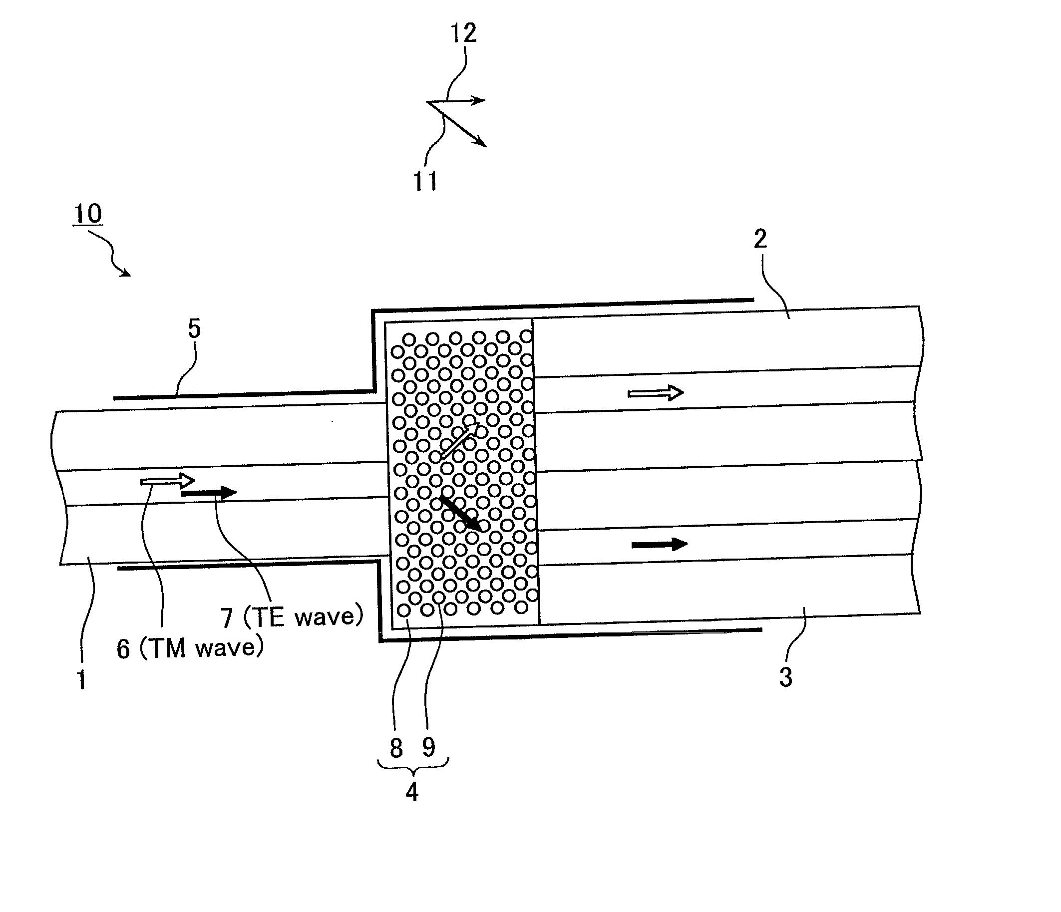
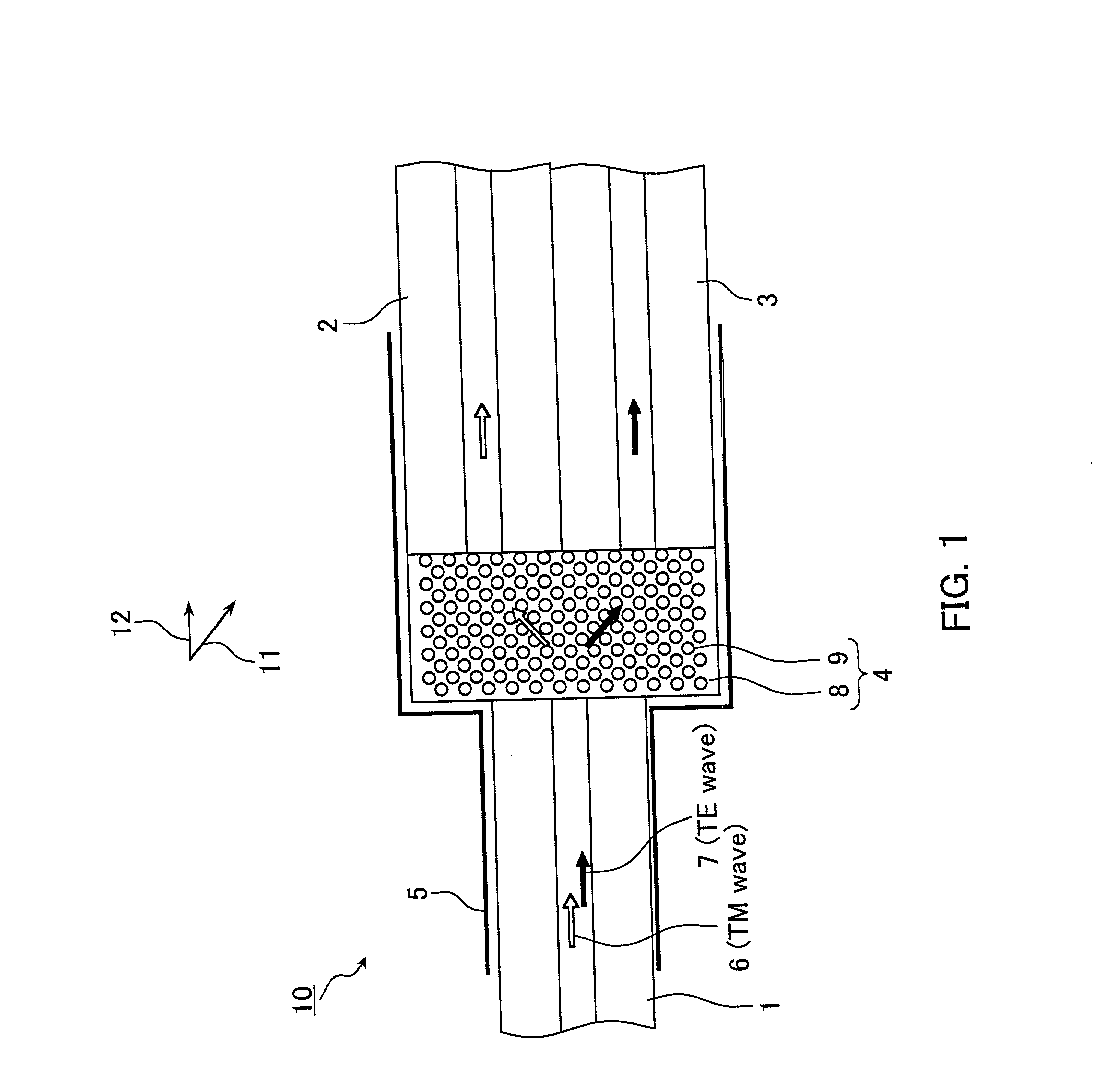
[0035] Embodiment 1 illustrates a demultiplexer as an example of an optical device according to the present invention. FIG. 1 schematically illustrates the configuration of an optical device 10 according to Embodiment 1. It should be noted that hatching lines have been omitted from Figures.
[0036] The optical device 10 includes an optical fiber 1 (F(0)) on the ingoing side, optical fibers 2 and 3 (F(1) and F(2)) on the outgoing side, a demultiplexing portion 4, and a guide 5. The guide 5 fixes the relative positions of the optical fibers 1 to 3 and the demultiplexing portion 4. The optical fibers 1 to 3 each include a core portion through which light propagates, and a cladding portion disposed around the core portion.
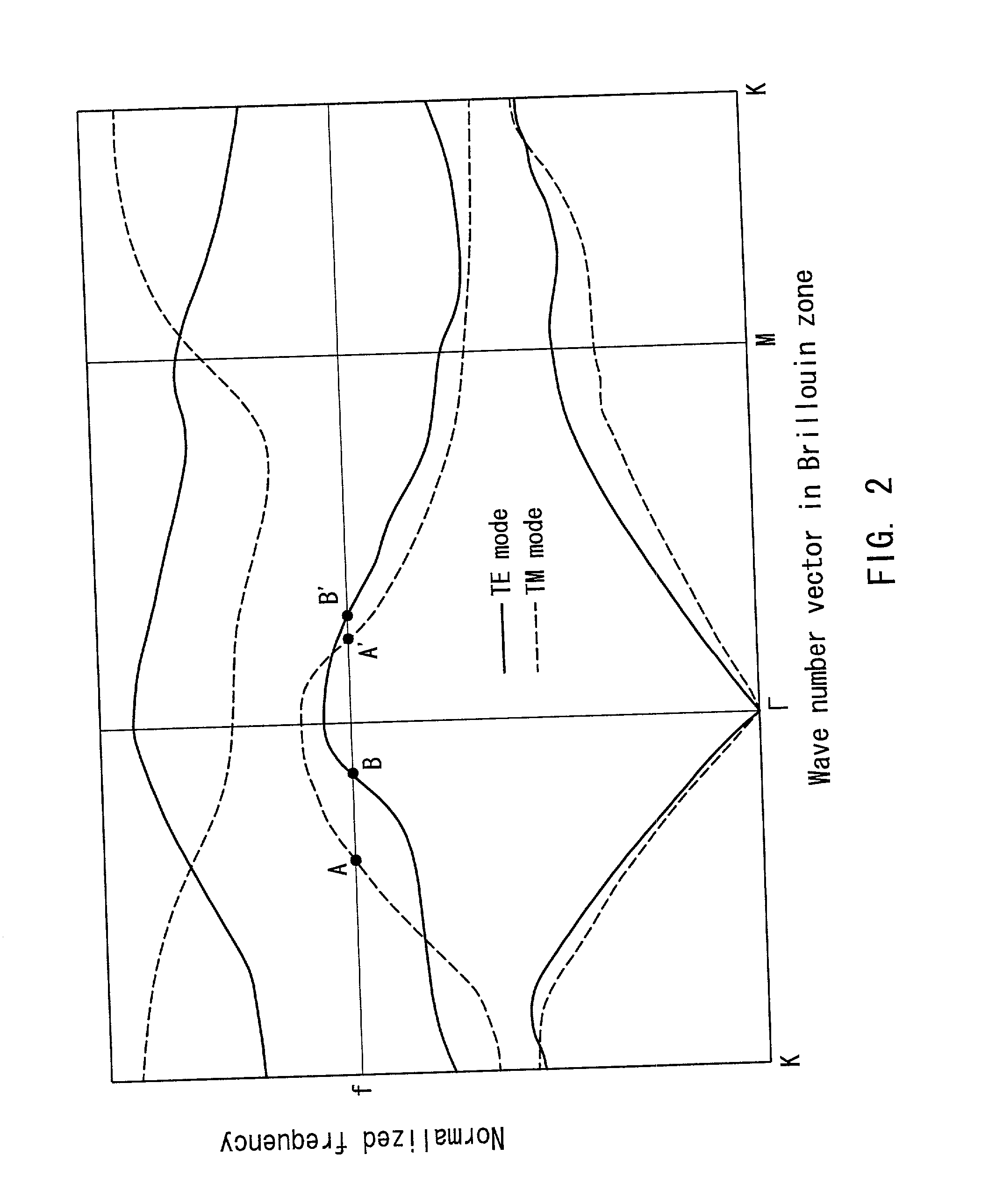
[0037] The demultiplexing portion 4 (also referred to as "first demultiplexing portion 4" in the following embodiments) is an optical member (first optical member) separating incident light of a wavelength .lambda. into a TE wave (ordinary light) and a TM wave (extraordi...
embodiment 2
[0046] Embodiment 2 illustrates a demultiplexer as an example of an optical device according to the present invention. FIG. 5A schematically illustrates the configuration of an optical device 50 of Embodiment 2. FIG. 5B illustrates the polarization state of the light emitted from the various optical components.
[0047] The optical device 50 includes an ingoing optical fiber 1, outgoing optical fibers 51 to 54, a first demultiplexing portion 4 (first optical member), a second demultiplexing portion 56 (second optical member), and a guide 57. The guide 57 fixes the relative positions of the optical fiber 1, the first demultiplexing portion 4, the second demultiplexing portion 56, and the optical fibers 51 to 54. The first demultiplexing portion 4, the second demultiplexing portion 56, and the optical fibers 51 to 54 are arranged such that light that is inputted by the optical fiber 1 is transmitted in that order.
[0048] The first demultiplexing portion 4 and the second demultiplexing por...
embodiment 3
[0053] Embodiment 3 illustrates a demultiplexer as an example of an optical device according to the present invention. FIG. 6A schematically illustrates the configuration of an optical device 60 of Embodiment 3. FIG. 6B illustrates the polarization state of the light emitted from the various optical components.
[0054] The optical device 60 is a 2n demultiplexer. The optical device 60 includes an ingoing optical fiber 1, outgoing optical fibers 61(1) to 61(2.sup.n-1) and 62(1) to 62(2.sup.n-1), n demultiplexing portions 63(1) to 63(n), and a guide 64. The guide 64 fixes the relative positions of the optical fiber 1, the optical fibers 61 and 62, and the demultiplexing portions 63.
[0055] The n demultiplexing portions 63(1) to 63(n) are optical members having a structure similar to the demultiplexing portion 4 in Embodiment 1. That is to say, these optical members include a first material 8 having an ingoing plane and an outgoing plane that are parallel to one another, and columnar port...
PUM
| Property | Measurement | Unit |
|---|---|---|
| wavelength | aaaaa | aaaaa |
| wavelength | aaaaa | aaaaa |
| separation angle | aaaaa | aaaaa |
Abstract
Description
Claims
Application Information
 - R&D
- Intellectual Property
- Life Sciences
- Materials
- Tech Scout
- Unparalleled Data Quality
- Higher Quality Content
- 60% Fewer Hallucinations
Browse by: Latest US Patents, China's latest patents, Technical Efficacy Thesaurus, Application Domain, Technology Topic, Popular Technical Reports.
© 2025 PatSnap. All rights reserved.Legal|Privacy policy|Modern Slavery Act Transparency Statement|Sitemap|About US| Contact US: help@patsnap.com


