Network management system

a network management and network technology, applied in the field of network management system, can solve the problems of wasteful processing, further wasteful processing, and wasteful processing

Active Publication Date: 2002-08-15
OKI ELECTRIC IND CO LTD
View PDF3 Cites 72 Cited by
  • Summary
  • Abstract
  • Description
  • Claims
  • Application Information

AI Technical Summary

Benefits of technology

[0010] It is another object of the present invention to control Quality of Service (QoS) of a packet transfer path in response to information about communication quality of the network in each of nodes and to reduce a load of processing being associated with the QoS control by each of nodes and by the network management unit, in the above network management system.
[0011] It is still another object of the present invention to perform processing of filtering a packet in each of nodes located in the packet transfer path and to reduce the load of processing being associated with the filtering processing by each of nodes and by the network management unit, in the above network management system.
[0012] It is still another object of the present invention to perform SLA (Service Level Agreement) management for a packet based on information acquired in each of nodes located in the packet transfer path and to reduce the load of processing being associated with the management by each of nodes and by the network management unit, in the above network management system.

Problems solved by technology

That is, irrespective of whether or not a packet passes through a node, setting to cause the node to provide information about the passage of the packet is needed, which is wasteful processing.
Moreover, the network managing device acquires information about the node through which the packet does not pass, which is also wasteful processing.
If such the processing is required, when the packet does not pass through the node, it means that further additional wasteful processing is performed.
Furthermore, as the number of nodes to be installed on the network increases, the number of the nodes from which information has to be acquired increases and, as a result, processing that has to be performed by the network managing system becomes complicated.
Same problems as described above occur not only in the connectionless network but also a connection oriented type network in which communications are carried out with the connection being established in advance.

Method used


Image

  • Network management system
  • Network management system
  • Network management system

Examples


first embodiment

[0159] (A-4) Modified Embodiment of First Embodiment

[0160] In the above first embodiment, a method for erasing the tracing packet MP1 being resident at each node is not described, however, by using the following method, for example, the tracing packet MP1 can be erased.

[0161] A first method is to erase the tracing packet MP1 being resident when the processing of sending the information collecting packet MP2 has been completed in each node. A second method is for the network management unit 4 to send out an erasing driving packet having a program to execute erasing operations, to the edge node 2-1. Each of the nodes, when having received the erasing driving-packet, makes the program run to erase the tracing packet being resident. A third method is to write time when the tracing packet MP1 or time while the tracing packet is resident in advance in the tracing packet MP1 and to control the time so that each of the nodes autonomously erases the tracing packet MP1 which is resident at ea...

second embodiment

[0164] (B) Second Embodiment

[0165] The network management system of the second embodiment of the present invention will be explained by referring to a drawing.

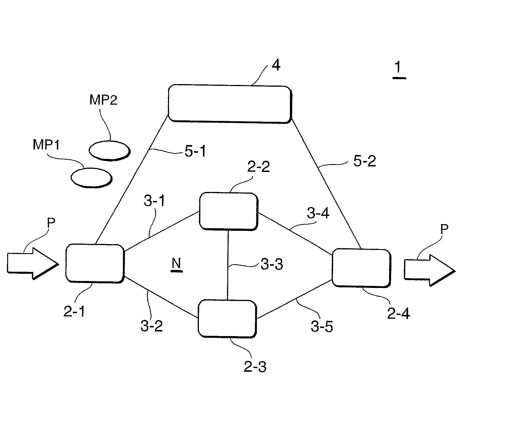
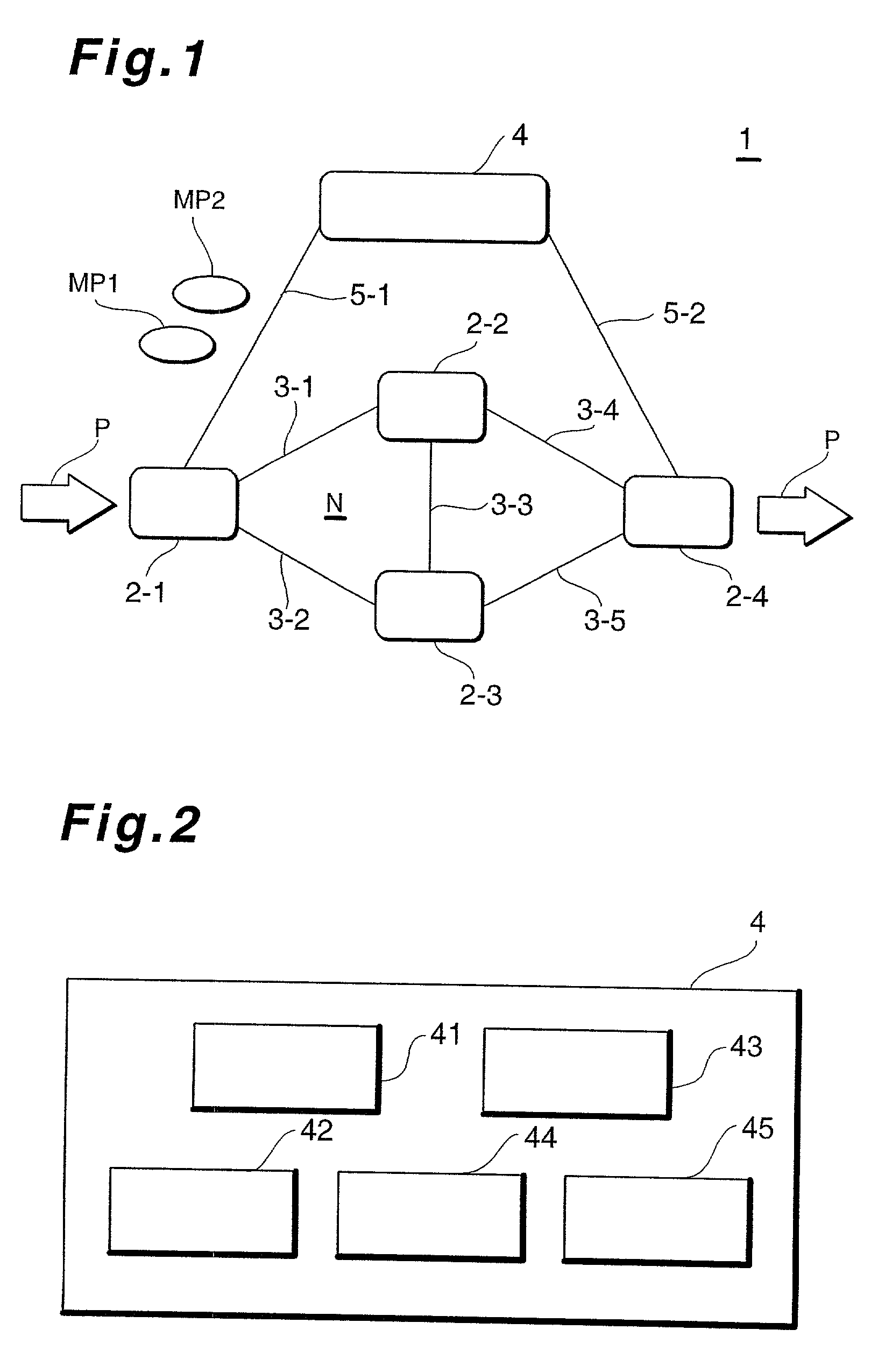
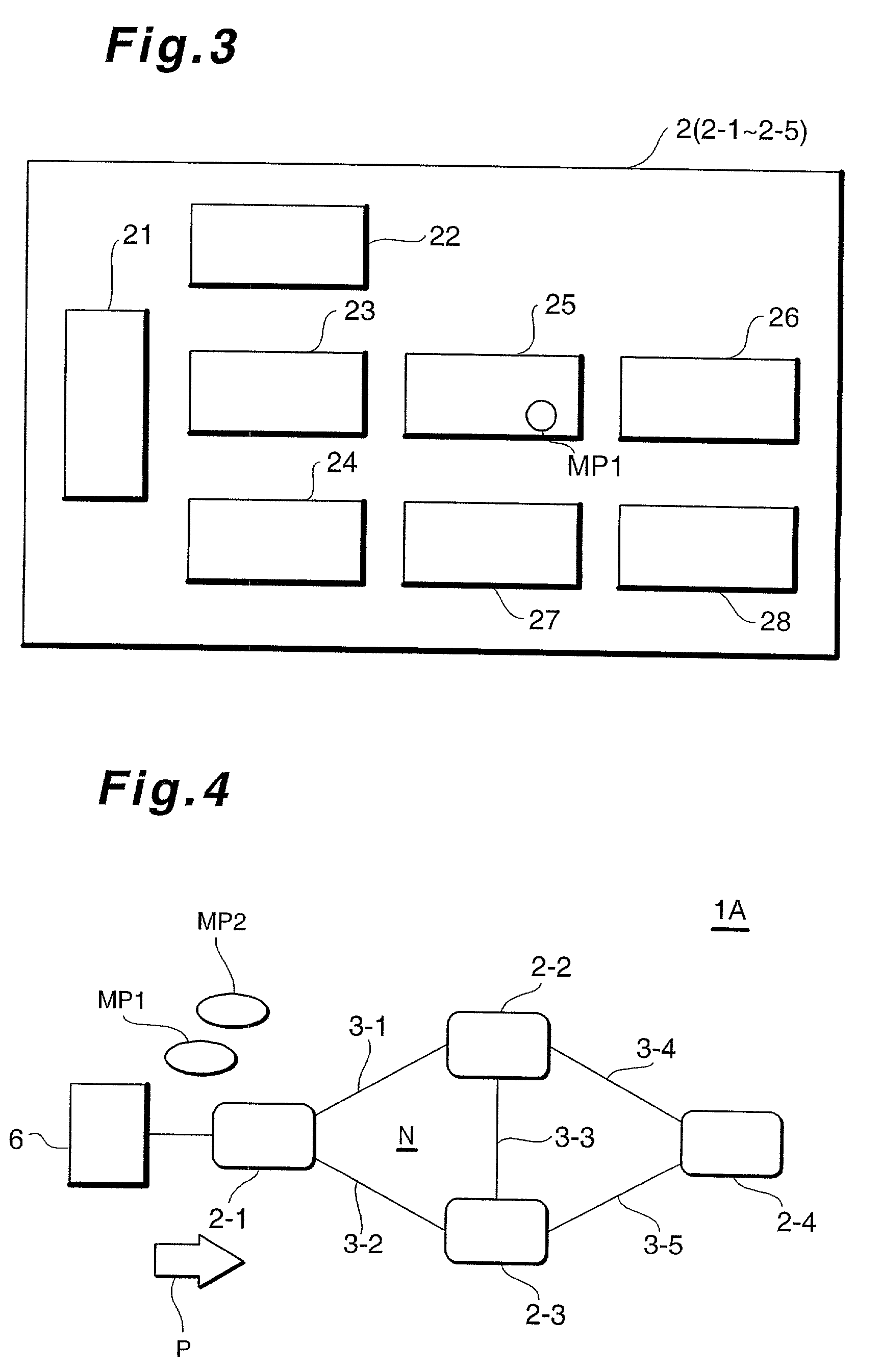
[0166] FIG. 4 is a block diagram showing configurations of a network management system of the second embodiment. In FIG. 4, same reference numbers are assigned to corresponding parts having the same functions as those in FIG. 1.

[0167] In the network management system 1A of the second embodiment shown in FIG. 4, instead of the network management unit 4 of the first embodiment shown in FIG. 1, a user terminal 6 being a sender of the transfer packet P is provided as a sender of the tracing packet MP1 and information collecting packet MP2. The user terminal 6 is connected to the edge node 2-1 on the introduction side.

[0168] Processing to be performed by each of nodes 2-1, . . . , and 2-4 is almost the same as those in the first embodiment, but is different on following points. That is, the node on the guiding-out edge node 2-4 for...

third embodiment

[0172] (C) Third Embodiment

[0173] The network management system of the third embodiment of the present invention will be explained by referring to drawings.

[0174] FIG. 5 is a schematic block diagram showing configurations of a network management system according to the third embodiment of the present invention. In FIG. 5, same reference numbers are assigned to corresponding parts having the same functions as those in FIGS. 1 and 4.

[0175] In the network management system 1B of the third embodiment, as in the case of the first embodiment, a network management unit 4 serves as a sender of the tracing packet MP1 and the information collecting packet MP2 and collects the information about the path, however, an instruction to collect the information about the path is provided from the user terminal 6 through links 5-3 to the network management unit 4 and the obtained information about the path is provided from the network management unit 4 through the link 5-3 to the user terminal 6.

[0176...


PUM


Abstract

A network management system is provided which is capable of reducing a load of processing to be performed by each of nodes when information about a path on a network in each of nodes is acquired. The network management system includes a first edge node serving as an entrance unit to a communication network, second edge node serving as an exit unit, relay node mounted between both the edge nodes and path information acquiring unit to send out a tracing signal used to trace a transfer signal along a transfer route to the first edge node and to obtain information about a path for the transfer signal. Each node is made up of a path information holding unit, tracing signal residing unit, and tracing signal sending unit. The path information acquiring unit acquires the information about the path on a transfer route from one node out of a plurality of nodes.

Description

[0001] 1. Field of the Invention[0002] The present invention relates to a network management system and more particularly to the network management system being suitable for acquiring information about a path through which a packet has passed in a network which is of a connectionless mode communication type.[0003] 2. Description of the Related Art[0004] In a general network management system, for example, a device adapted to manage the network acquires information about connection among transmission paths housed in units making up nodes on the network and about packets having passed through the transmission paths and, based on the acquired information, produces information about a path of a network through which a packet has passed, that is, information indicating contents of the packet having passed through the path and kinds or numbers of the paths through which the packet has passed and holds the information. Such conventional technology is disclosed in Japanese Patent Applicatio...

Claims


Application Information

Patent Timeline
Patent Type & Authority Applications(United States)
IPC IPC(8): H04L12/24H04L12/851
CPCH04L41/5003H04L43/10H04L47/2425
Inventor KATO, KEI
Owner OKI ELECTRIC IND CO LTD
Why Eureka
Try Eureka