Automatic weapon user identification and safety module

a technology for user identification and safety modules, applied in the direction of safety arrangements, weapons components, electrical equipment, etc., can solve the problems of reducing the effectiveness of firearms in emergency situations, operation by a person, injury or death,

Inactive Publication Date: 2002-08-22
QUANTUM LEAP RES
View PDF0 Cites 58 Cited by
  • Summary
  • Abstract
  • Description
  • Claims
  • Application Information

AI Technical Summary

Problems solved by technology

One of the dangers associated with firearms is that they may be operated by a person other than the owner of the firearm.
A situation which all too frequently arises is that a firearm is taken from a police officer (the authorized user) by an unauthorized user and used against the police officer, resulting in injury or death.
However, this mechanism reduces the effectiveness of the firearm in emergency situations and does not prevent the firearm from being used by an unauthorized user once the firearm is enabled.
The drawback of these systems is that, for example, a police officer requires that the firearm be enabled immediately, particularly when facing a suspect.
Fingerprint and voice recognition systems still have a high probability of rejecting the authorized user due to an incorrect measurement, or large variations in the biometric sample (due to, for example, stress), which can have disastrous effects for the police officer.
Furthermore, these systems require more response time depending on the accuracy and precision of the recognition template.
The user is expected to disable the firearm by triggering the RF signal, which is unsafe in an emergency situation or in the case where the authorized user is unconscious.
This system has an important drawback in that the transmitter consumes a great amount of power since it is continuously transmitting.
Accordingly, small batteries, suitable for incorporation into a small transmitter and receiver, are not adequate to provide long operational life.
This leads to high power consumption and a severe limitation on the time allowed for encryption, anti-jamming protocols, and mechanical blocking of the trigger.

Method used


Image

  • Automatic weapon user identification and safety module
  • Automatic weapon user identification and safety module
  • Automatic weapon user identification and safety module

Examples


Embodiment Construction

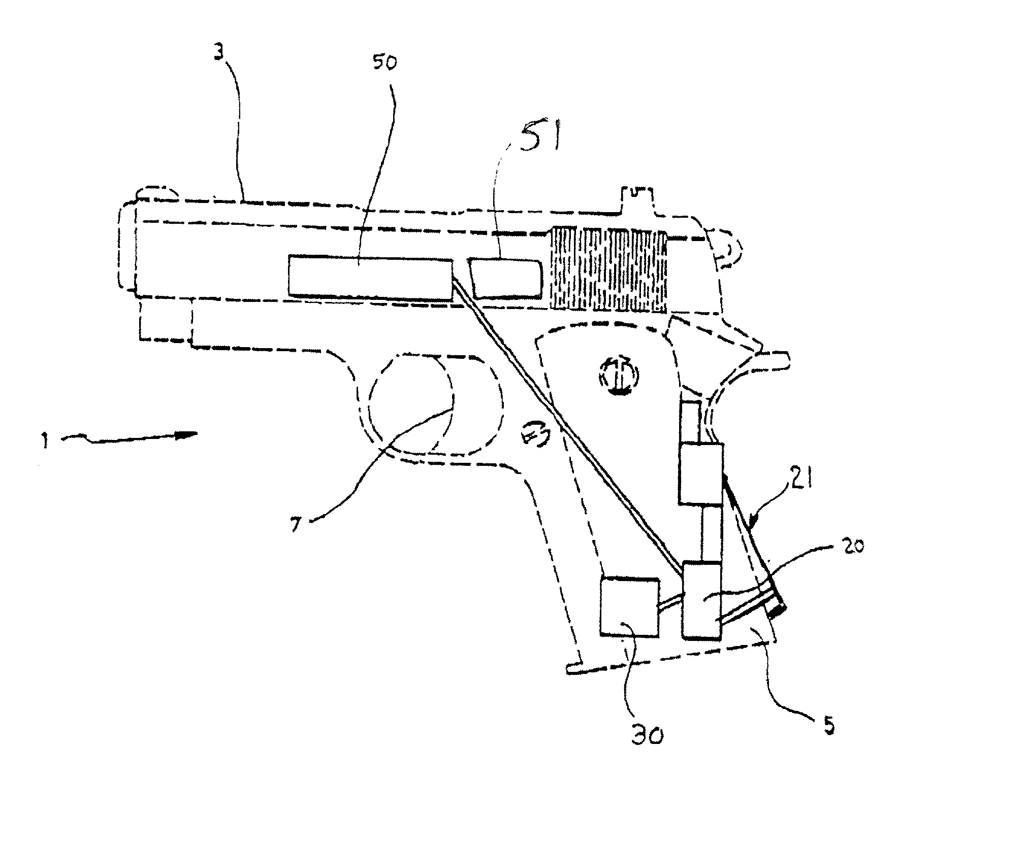
[0021] As mentioned above, the invention is directed to an automatic safety system for a weapon 1. In the context of the present invention, weapon includes firearms such as rifles, handguns, pistols, etc., and also includes stun guns, and, more broadly, any weapon which includes a handgrip for a user to grip. The invention may easily be adapted to any type of weapon 1, with the proper modifications. For the purposes of explaining the functioning of the present invention, it will be described as incorporated in a handgun 1, shown in FIG. 1. The handgun 1 has a barrel 3, a handgrip 5, a trigger 7 and a firing mechanism, all of which are well known. However, it should be understood that the following description is equally applicable for any type of weapon.

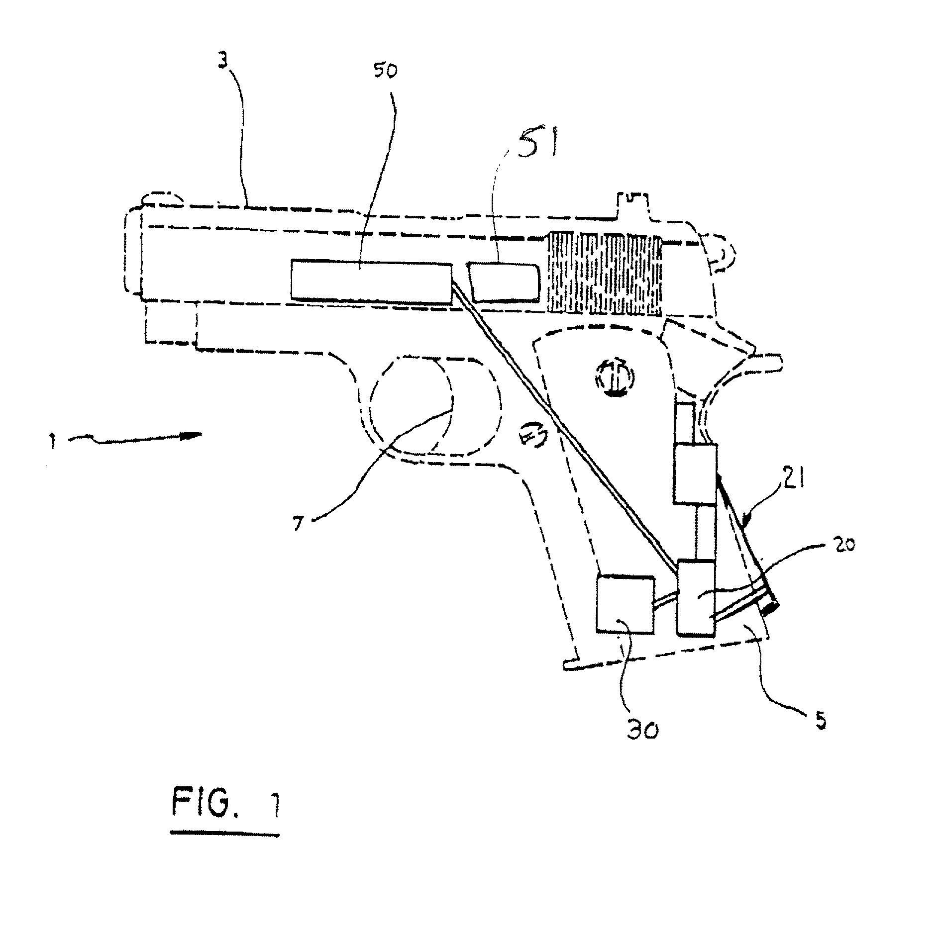
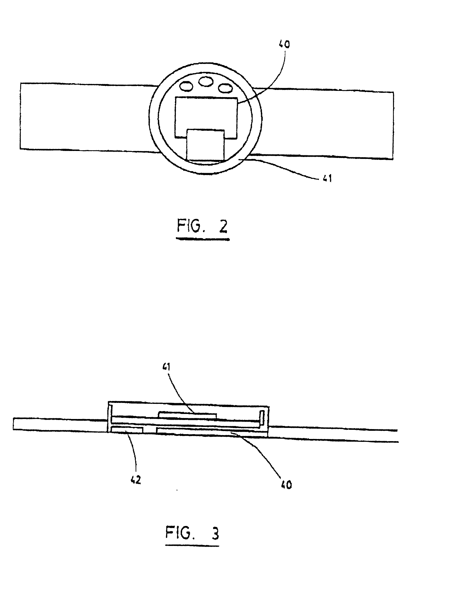
[0022] The system according to a preferred embodiment thereof includes a unit which is integrated into the firearm 1, and at least one token 40 which is remote from the firearm 1. The unit which is integrated into the firearm is some...


PUM


Abstract

An automatic weapon safety system where power consumption is reduced and safety is increased is disclosed. The system includes a movement detector operatively associated with the handgrip of a weapon for detecting the presence of a hand on the handgrip. The system also has a transceiver operatively associated with the movement detector for sending a coded signal when the weapon has been gripped. The coded signal is received by at least one remote token which receives the coded signal and transmits a coded acknowledgement signal upon receipt of the coded signal. A system is provided for enabling and disabling the weapon, operatively connected to the transceiver for allowing operation of the weapon when the coded acknowledgement signal has been received. The system may include two tokens, which are worn by the authorized user. In this case, the transceiver further includes an anti-collision module to discriminate between the different tokens and select which one will be permitted to issue the coded acknowledgement signal. Also preferably, the transceiver includes an anti-jamming module. Verification of the token can be done every time the trigger is depressed. Alternately, verification can be done only once, when the weapon is first gripped, and authorization remains until the handgrip is let go. Furthermore, since bi-directional RF communication is effected only when the trigger is depressed, power consumption is reduced.

Description

[0001] The present invention relates to an automatic weapon user identification and safety module.DESCRIPTION OF THE PRIOR ART[0002] One of the dangers associated with firearms is that they may be operated by a person other than the owner of the firearm. In the context of the present invention, this other person will be hereinafter referred to as "unauthorized user" and the owner, or person authorized to operate the firearm will be hereinafter referred to as "authorized user".[0003] A situation which all too frequently arises is that a firearm is taken from a police officer (the authorized user) by an unauthorized user and used against the police officer, resulting in injury or death. However, it should be understood that the present invention is equally applicable to any other situation where an unauthorized user takes control of a firearm.[0004] Many patents have been proposed to attempt to solve this problem. These patents describe different safety mechanisms to prevent the disch...

Claims


Application Information

Patent Timeline
Patent Type & Authority Applications(United States)
IPC IPC(8): F41A17/06F41C27/00
CPCF41A17/066H04K3/20H04K2203/24
Inventor HARLING, GORDFRYDMAN, HERSHELMILLER, RODNEY
Owner QUANTUM LEAP RES
Why Eureka
Try Eureka