Model train control system

Inactive Publication Date: 2002-08-22
KATZER MATTHEW A
View PDF0 Cites 28 Cited by
  • Summary
  • Abstract
  • Description
  • Claims
  • Application Information

AI Technical Summary

Problems solved by technology

In addition by queuing by commands at a single resident external controlling interface permits controlled execu

Method used


Image

  • Model train control system
  • Model train control system
  • Model train control system

Examples


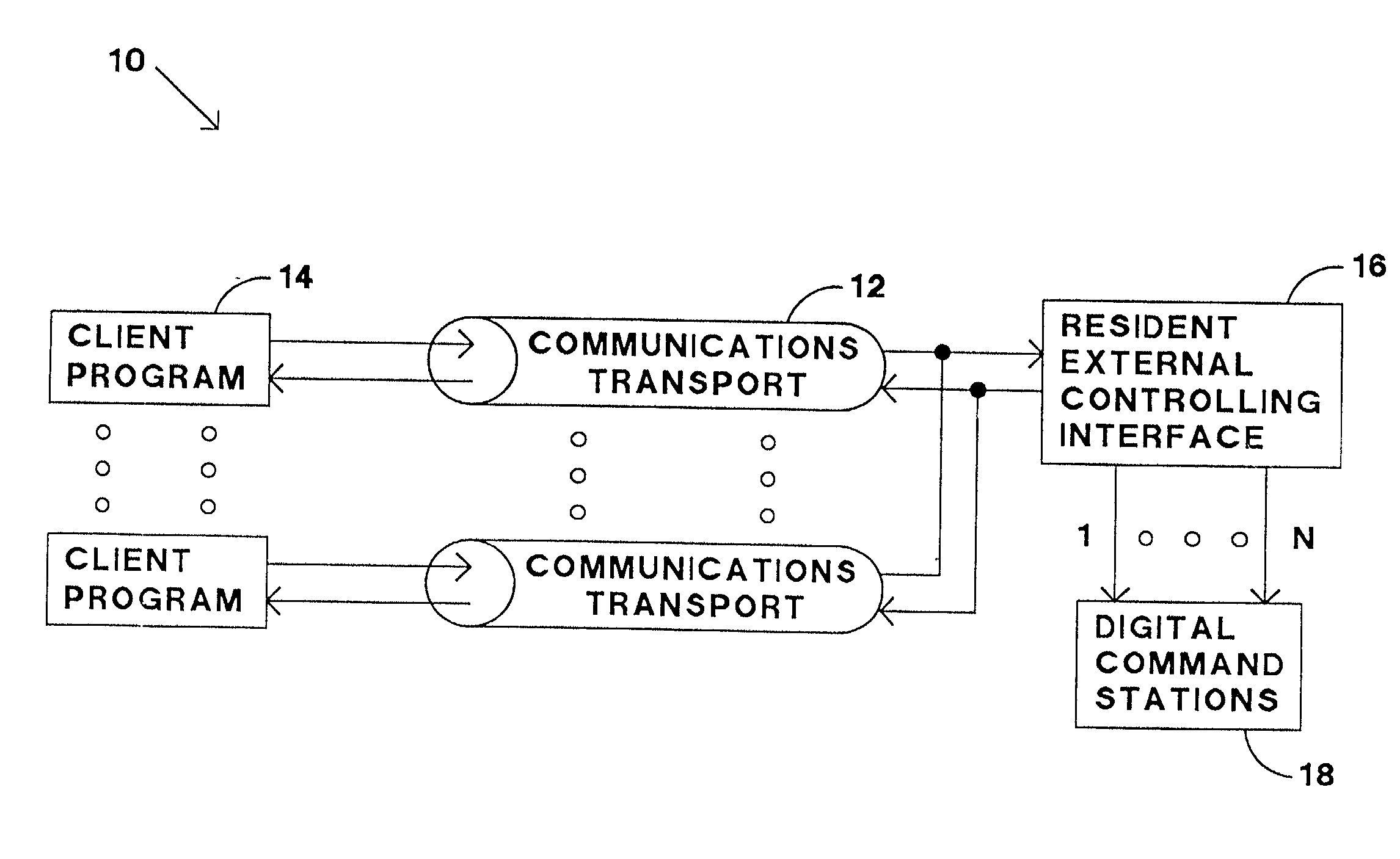
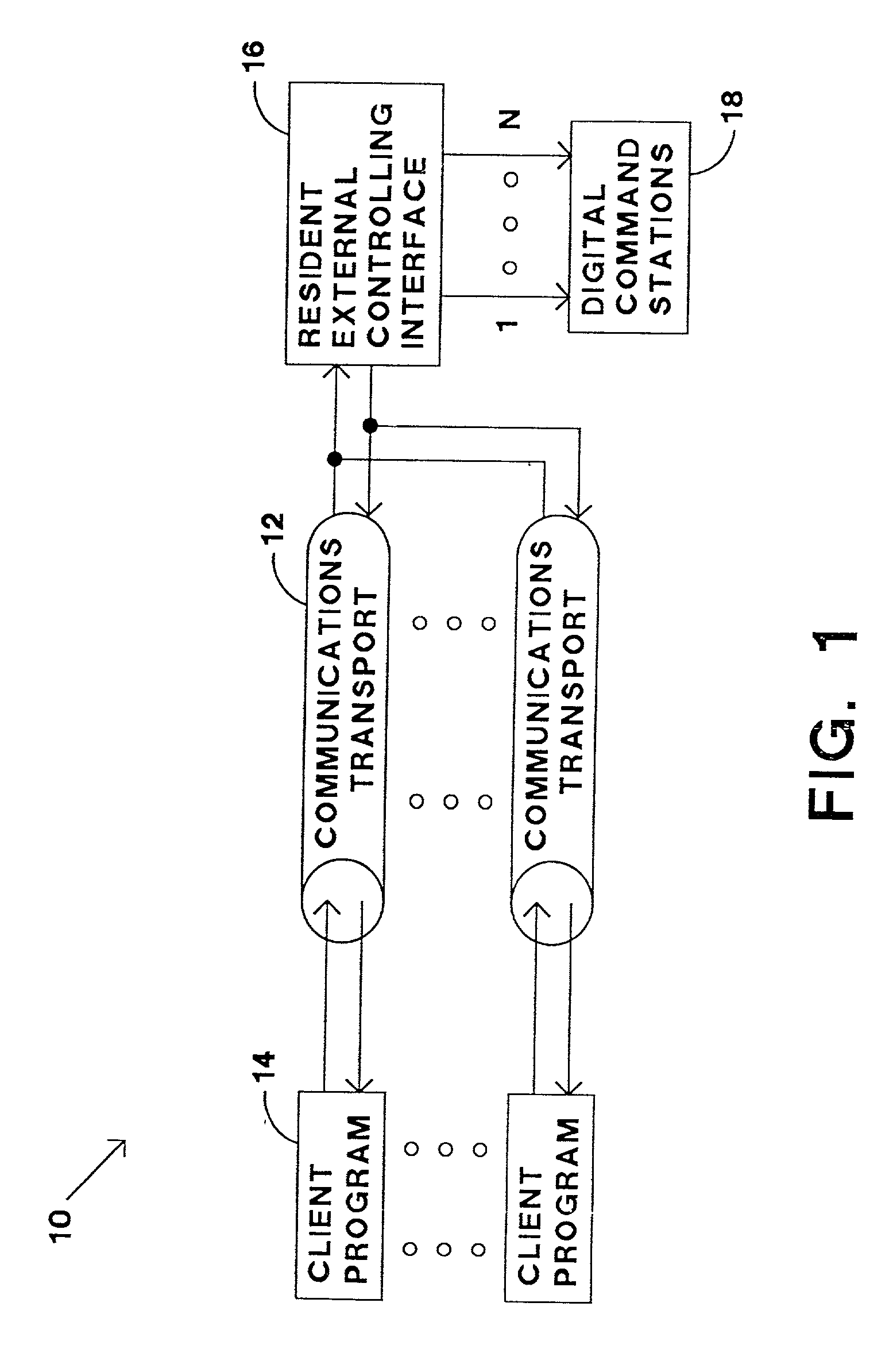
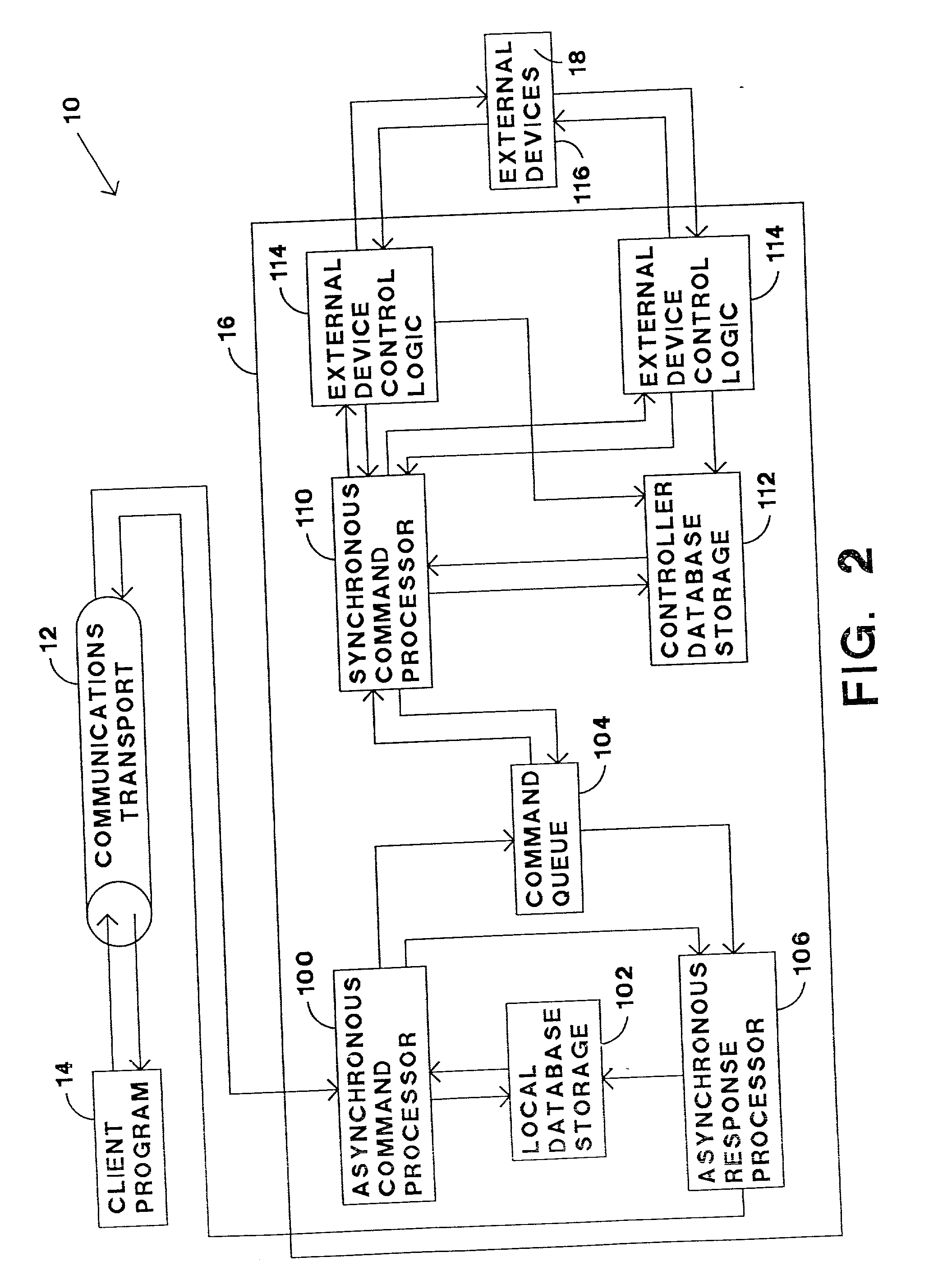
Embodiment Construction

2.2 Visual BASIC Throttle Example Source Code 3. IDL COMMAND REPERENCE 3.1 Introduction 3.2 Data Types 3.3 Commands to access the server configuration variable database KamCVGetValue KamCVPutValue KamCVGetEnable KamCVPutEnable KamCVGetName KamCVGetMinRegister KamCVGetMaxRegister 3.4 Commands to program configuration variables KamProgram KamProgramGetMode KamProgramGetStatus KamProgramReadCV KamProgramCV KamProgramReadDecoderToDataBase KamProgramDecoderFromDataBase 3.5 Commands to control all decoder types KamDecoderGetMaxModels KamDecoderGetModelName KamDecoderSetModelToObj KamDecoderGetMaxAddres KamDecoderChangeOldNewAddr KamDecoderMovePort KamDecoderGetPort KamDecoderCheckAddrInUse KamDecoderGetModelFromObj KamDecoderGetModelFacility KamDecoderGetObjCount KamDecoderGetObjAtIndex KamDecoderputAdd KamDecoderPutDel KamDecoderGetMfgName KamDecoderGetPowerMode KamDecoderGetMaxSpeed 3.6 Commands to control locomotive decoders KamEngGetSpeed KamEngPutSpeed KamEngGetSpeedSteps KamEngPutSp...


PUM


Abstract

A system which operates a digitally controlled model railroad transmitting a first command from a first client program to a resident external controlling interface through a first communications transport. A second command is transmitted from a second client program to the resident external controlling interface through a second communications transport. The first command and the second command are received by the resident external controlling interface which queues the first and second commands. The resident external controlling interface sends third and fourth commands representative of the first and second commands, respectively, to a digital command station for execution on the digitally controlled model railroad.

Description

[0001] The present invention relates to a system for controlling a model railroad.[0002] Model railroads have traditionally been constructed with of a set of interconnected sections of train track, electric switches between different sections of the train track, and other electrically operated devices, such as train engines and draw bridges. Train engines receive their power to travel on the train track by electricity provided by a controller through the track itself. The speed and direction of the train engine is controlled by the level and polarity, respectively, of the electrical power supplied to the train track. The operator manually pushes buttons or pulls levers to cause the switches or other electrically operated devices to function, as desired. Such model railroad sets are suitable for a single operator, but unfortunately they lack the capability of adequately controlling multiple trains independently. In addition, such model railroad sets are not suitable for being control...

Claims


Application Information

Patent Timeline
IPC IPC(8): A41D13/00A63H19/24
CPCA63H19/24A63H2019/243
Inventor KATZER, MATTHEW A.
Owner KATZER MATTHEW A
Why Eureka
Try Eureka