
Light beam scanning pen, scan module for the device and method of utilization

a scanning pen and light beam technology, applied in the field of beam scanning, can solve the problems of many repeated reading attempts, virtually no depth of field of the device, and limited contact reading

Inactive Publication Date: 2002-09-12
SYMBOL TECH INC
View PDF0 Cites 41 Cited by
  • Summary
  • Abstract
  • Description
  • Claims
  • Application Information

AI Technical Summary

Benefits of technology

[0042] Yet another object of this invention is to provide a scanning method utilizing a non-contact, wide-angle beam scanner "pen" in which a beam is caused to scan its target several hundred times per second, thereby allowing the user to raster the scan across a two-dimensional bar-code with relatively slight movement of the body part employed to hold the device.
[0045] A further object of the invention is to provide compact scan modules and elements packageable into equipment as small as a pen for use in miniature scanning applications.

Problems solved by technology

It is light, rugged and easy to hold, but its use is confined to reading smooth flat surfaces with relatively high quality printed bar-code.
Because of this short focal length the device has virtually no depth of field and a major drawback of being essentially limited to contact reading.
Surface damage often results in many repeated reading attempts as well as poor productivity.
Contact-type scan wands are also poorly suited to scanning printed material that has damage (as coupons usually do when carried around in a purse), or when the surface that is labeled or printed upon is curved, soft, irregular or wrinkled such as mailing pouches, or with other generally non-flat surfaces upon which bar-code is printed.
Consequently, these are more effective for reading bar-codes printed on irregular surfaces, but have the drawback of being far bulkier than contact wands.
The gun-type scanners have ergonomic characteristics similar to those of a hand gun, yet are generally bulkier; in many cases, they are more like a hand-held hair dryer and are not amenable to being carried in a pocket or to storage in a cash drawer.
The aim and shoot characteristics of the gun-type device are suited for long range bar-code reading on the order of a few feet, but remain clumsy for short range reading jobs where distances of about six inches to one foot are involved, especially when the user is seated at a desk or counter.
In such cases, the ergonomic benefits are lost and become liabilities.
Because of its size and handling requirements, numerous problems associated with the pistol-grip aim and shoot design result.
With these functional demands placed on the user, difficulty of operation increases significantly with any physiological impairments or severance of digits the operator may have.
Of course, users with substantial disability impairing their ability to grip at all, are entirely precluded from using aim and shoot type pistol grip devices.
Because of its weight, dimensions and triggering mechanics, other methods of holding and moving the device without using the hand and fingers to grip and manipulate are ungainly.
Pistol grip aim and shoot scanners create special problems for users with disabilities, and reasonable accommodation problems for employers under the new Americans with Disabilities Act.
Another problem is realized when observing the extent to which an able-bodied user's gripping hand is monopolized by the holding and operation of the gun.
This can cut into productivity significantly and impede the flow of work.
Another problem associated with aim and shoot devices is that they typically require operators working at counters to pull their using arm back at the elbow so that the end of the gun clears the surface of the label they are attempting to scan.
Apart from being unsound from a general human factors viewpoint, this extra movement can create discomfort for people with arthritis, bursitis, and other diseases, injuries or disabilities affecting the articulations of the shoulder.
The problem is worsened if the operator needs to be seated at a counter.
The very shape of gun-type scanners can pose safety concerns in some instances, such as an employee working on a late shift in a warehouse carrying and using the gun, wherein contract security personnel might become unduly alarmed by the pistol-like appearance, especially when observed at a distance.
This is extremely difficult, since bar-code labels are typically about the size of a large postage stamp.
Also, relatively minor curves in the scan line caused by the amplification of normal hand movement as a function of target distance may throw off the time values assigned to each element of the bar code and result in a bad scan.
Repeated attempts are more and more likely to be poor as well, as the result of natural hand-arm fatigue and frustration.
This device was therefore not very successful commercially.
The fingers are freed from the arresting level of involvement required to operate a pistol-grip mechanism, yet the design is nonetheless ungainly because the back of the hand is not well-suited to aiming the beam.
Generally, CCD readers must be placed on top of and cover the target bar-code, have poor depth of field and are limited as to the size of bar-codes to be read, and thus possess many of the limitations of contact readers.
Experimental CCD systems with expensive large lens focusing systems can achieve modest improvements in the depth of field, but are bulkier and expensive.
Owing to a complex optical path with ample head room requirements for the beam to escape, these scanners are bulky and at best may be packaged in boxes or gun shaped housings, but not smaller.
Because of the size of the motors required, this system is ill suited to hand-held scanners.
It has a limited range of scan patterns, all of which include a significantly curved path of the moving beam; it cannot produce a line or raster scan.
Also, because of motor inertia, this system is ill suited to the intermittent operation characteristic of a hand-held scanner.
Existing fixed mount scanners are not amenable to mounting on robot arms for use on production lines because of their size and weight.
Reluctance of employees to accept new bar-code scanning applications because of the clumsiness or inconvenience of the equipment is also an important issue.
For example, nurses, in the course of their patient care duties, have been resistant to the idea of using bulky bar code readers because of the clumsiness and inconvenience of the devices.
Other problems with prior art devices stem from the inability to mount them in tiny housings because of the space consuming clearance requirements associated with non-axial optical designs.
Even so this scan engine is too bulky to fit into a pen-size housing and cannot produce two dimensional scan patterns.
It suffers from the common optical layout problem of having to provide ample head room for the emerging scan beam.
None of the known moving beam or CCD scanning systems which can automatically scan one or two dimensions in order to read information is small enough to be packaged into a housing having the general size and shape of a pen or wand.

Method used


Image

  • Light beam scanning pen, scan module for the device and method of utilization
  • Light beam scanning pen, scan module for the device and method of utilization
  • Light beam scanning pen, scan module for the device and method of utilization

Examples


Embodiment Construction

[0069] As has been described, prior art hand-held non-contact laser scanners such as the gun-type scanners have been bulky, heavy, and accordingly less than optimal in their ergonomic characteristics. Because of their size and shape, they have been designed and are suitable for use by gripping in the palm of the user's hand. Non-scanning bar-code readers such as the contact wand type have superior ergonomics but are limited in their applicability because of their requirements for contact with the bar-code and physical sweeping movement by the user.

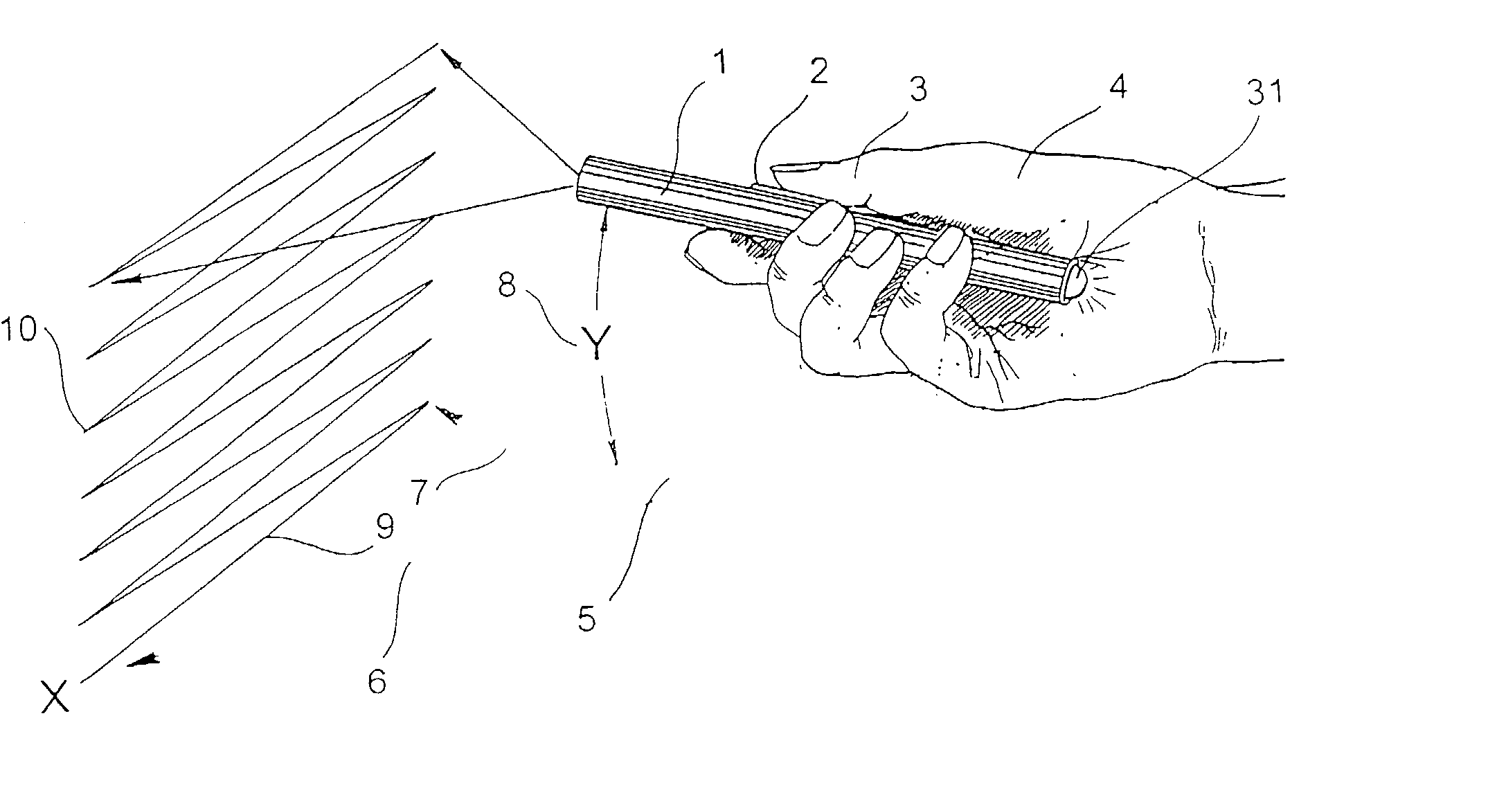
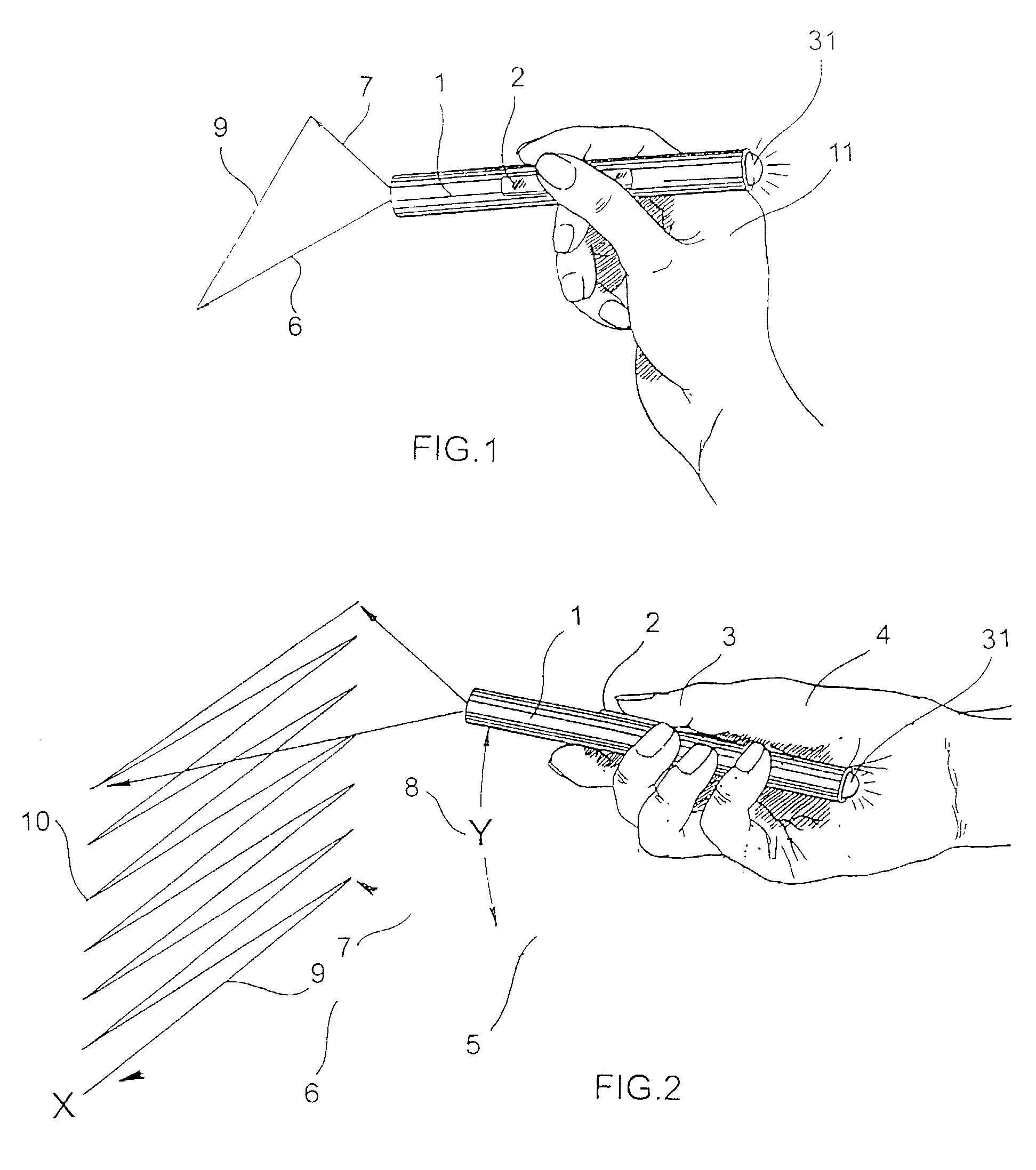
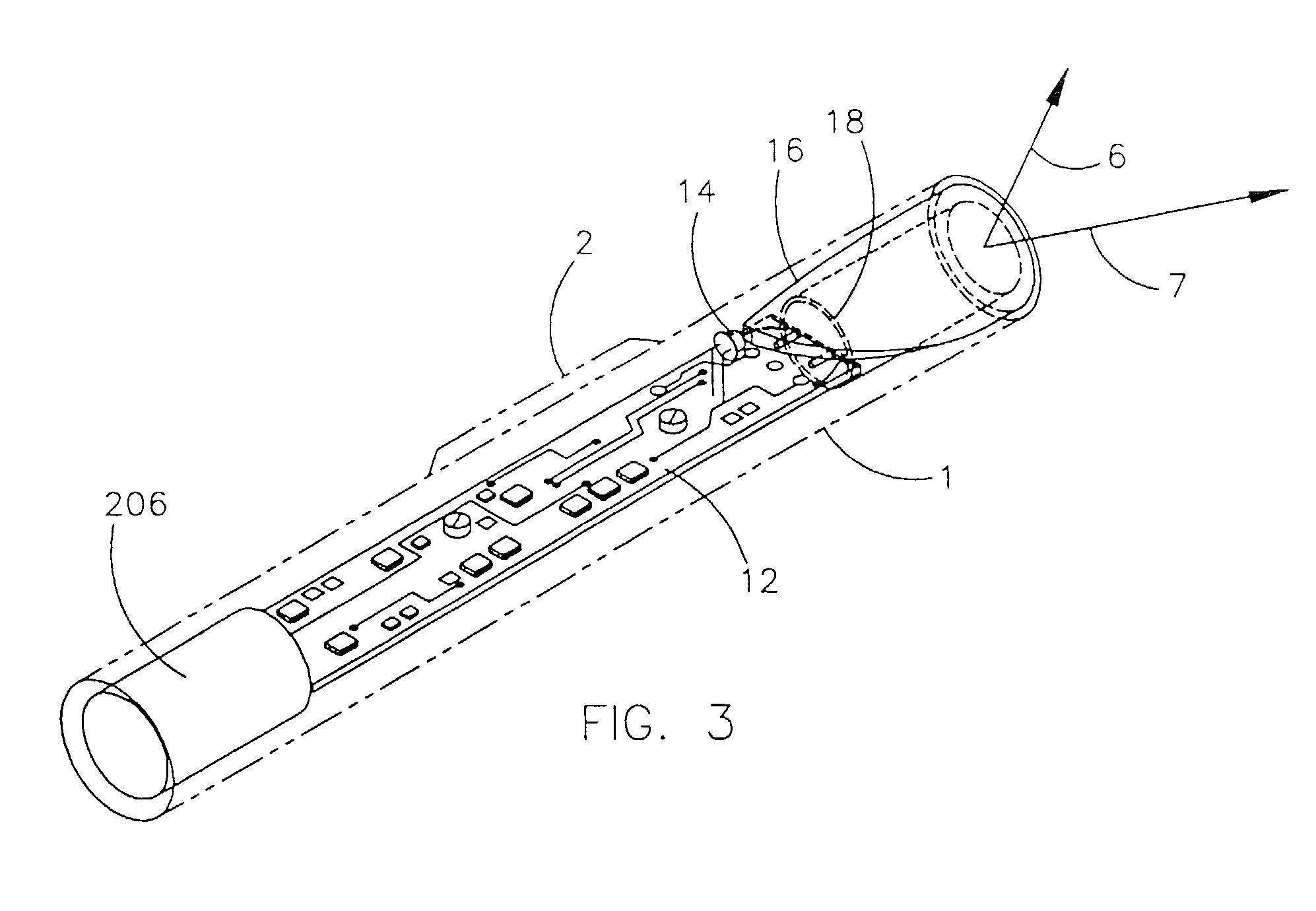
[0070] The present invention provides a non-contact scanner which is housed in an elongated housing which can comfortably be grasped in the fingers in the same manner in which a pen is grasped, as shown in FIG. 1, or the manner in which a wand is grasped, as shown in FIG. 2. A pen-style housing 1 is shown in FIG. 1, which is elongated along an axis A and may conveniently have a length L along axis A of between about 5 inches and about 7 in...


PUM


Abstract

A high speed non-contact beam scanning device sized and shaped to provide the ergonomic benefits of a pen or wand, yet can scan a wide angle moving beam across an information-bearing target in one or two dimensional scan patterns such as lines, rasters or other patterns in order to read information therefrom. The device is well suited for reading one or two dimensional bar-code or other printed matter. In order to achieve the high density optical packaging necessary for its high performance to size benefits the device employs a novel in-line or "axial" gyrating, or "axial" scan element. The axial scan element can accept an input light beam at one end and cause it to emerge from its opposite end as a scanned beam, propagating in the same general forward direction it had upon entering the element. Reflected light, which carries information contained on the target, is collected by an internal non-imaging light collector and is processed by signal processing electronics. All components are integrated into a thin low mass module small enough to fit in a pen. Communication from the device is achievable by a cable or by wireless means.

Description

[0001] This is a continuation-in-part of U.S. patent application Ser. No. 07 / 776,663 entitled "Electro-Optical Scanning System With Gyrating Scan Head", filed Oct. 15, 1991, and of Ser. No. 08 / 006,754 filed Jan. 21, 1993, which is a continuation-in-part of Ser. No. 07 / 612,983, filed Nov. 15, 1990, now U.S. Pat. No. 5,187,612, issued Feb. 16, 1993 entitled "Gyrating Programmable Scanner".FIELD OF THE INVENTION[0002] The field of beam scanning for the purpose of gathering information is rapidly advancing. The commercial application and importance of bar-code reading is well known and is now becoming more sophisticated with the introduction of high density two dimensional bar-code. Code 49 Code 1 and PDF 417 are examples of new bar-code standards that contain information in a two dimensional array.[0003] As information densities increase, scanning with high speed scan patterns becomes necessary in order to read them rapidly. In addition to bar-code reading, the ability to read alphanum...

Claims


Application Information

Patent Timeline
Patent Type & Authority Applications(United States)
IPC IPC(8): G02B3/14G02B26/10G02B26/12G06K7/10H02K7/06H02K7/065H02K26/00H02K33/16H03K17/94H03K17/96
CPCG02B3/0087G02B5/001G02B13/001G02B26/10G02B26/101G02B26/105G02B26/121G06K7/10594G06K7/10643G06K7/10653G06K7/10673G06K7/10762G06K7/10772G06K7/10811G06K7/10871G06K7/10881G06K2207/1013G06K2207/1016G06K2207/1017H02K7/06H02K7/065H02K26/00H02K33/16H02K2201/12
Inventor PLESKO, GEORGE A.
Owner SYMBOL TECH INC
Learn More