
Vibrating piece, vibrator, oscillator, and electronic device

Inactive Publication Date: 2002-09-12
SEIKO EPSON CORP
View PDF1 Cites 36 Cited by
  • Summary
  • Abstract
  • Description
  • Claims
  • Application Information

AI Technical Summary

Benefits of technology

[0034] An object of the present invention is to provide a vibrating reed in which the ratio of CI values is maintained constant while minimizing the CI value of the fundamental wave, variations of the CI values between the vibrating piece devices are reduced even if the base is made short, and the entire vibrating piece can be made smaller.

Problems solved by technology

If a device such as a vibrator picks up a signal of this harmonic wave by mistake for a signal of a frequency of a fundamental wave, this may cause the device to malfunction.
Thus, the risk that a device, etc., erroneously picks up a signal of a harmonic wave becomes small, and a high-performance vibrating piece is formed.
In this fundamental wave, if the CI value becomes too great, the performance of the vibrating piece may be caused to deteriorate.
However, if the CI value of the harmonic wave is increased to such a degree that the CI value of the fundamental wave is not increased too much, it is not easy that the CI value ratio is made to be 1.0 or more.
Therefore, a problem inevitably arises in that the CI value of the fundamental wave is increased more than necessary.
However, there are problems described below.
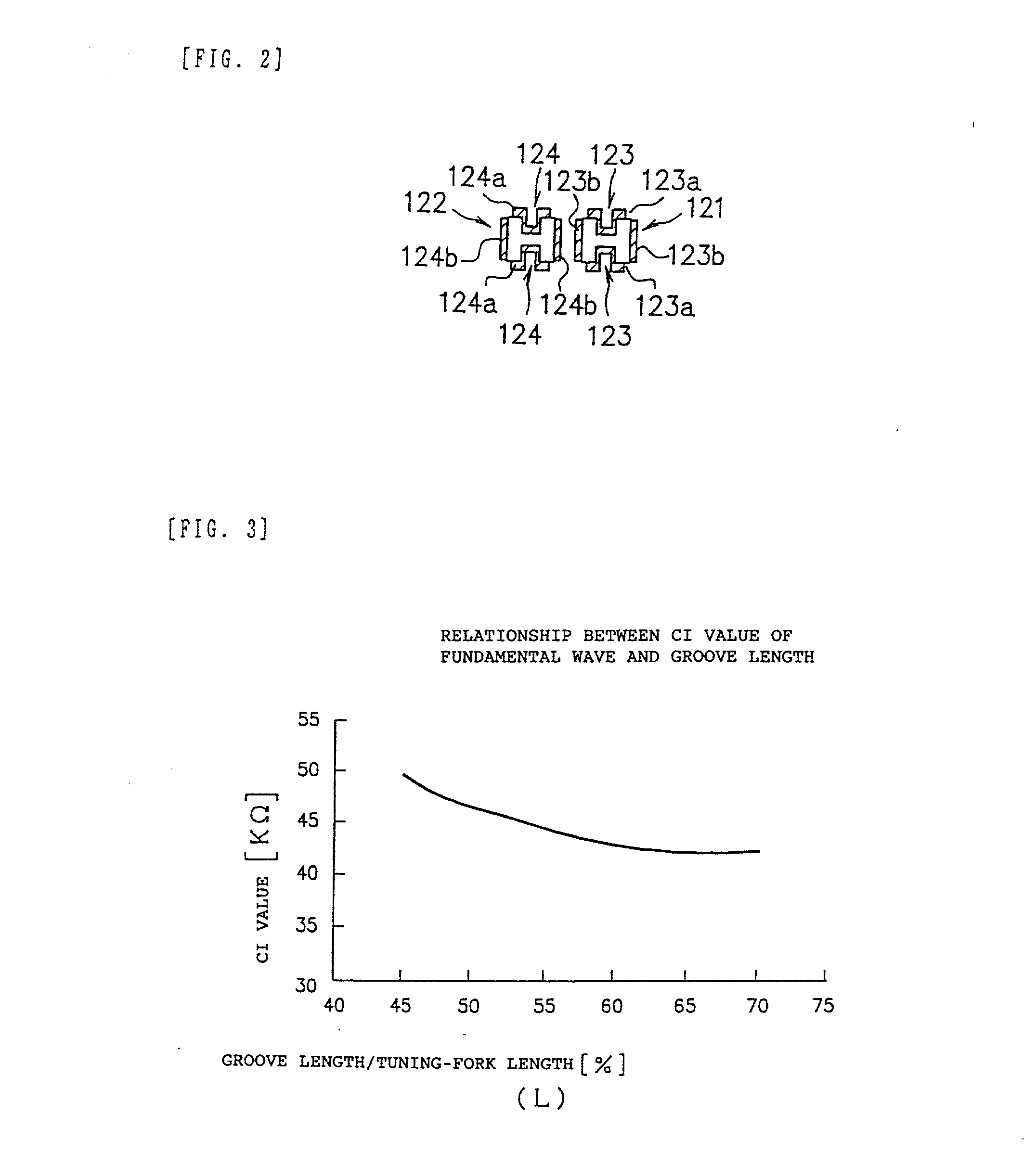
That is, generally, unless the length of the base 11 is made to be 40% or more of the length of the vibration arm sections 12 and 13, the CI value is not stabilized, and a problem arises in that the performance of the vibrating piece is deteriorated.
As a consequence, this has been an obstacle for reducing the size of the vibrating piece 10 itself.

Method used


Image

  • Vibrating piece, vibrator, oscillator, and electronic device
  • Vibrating piece, vibrator, oscillator, and electronic device
  • Vibrating piece, vibrator, oscillator, and electronic device

Examples


first embodiment

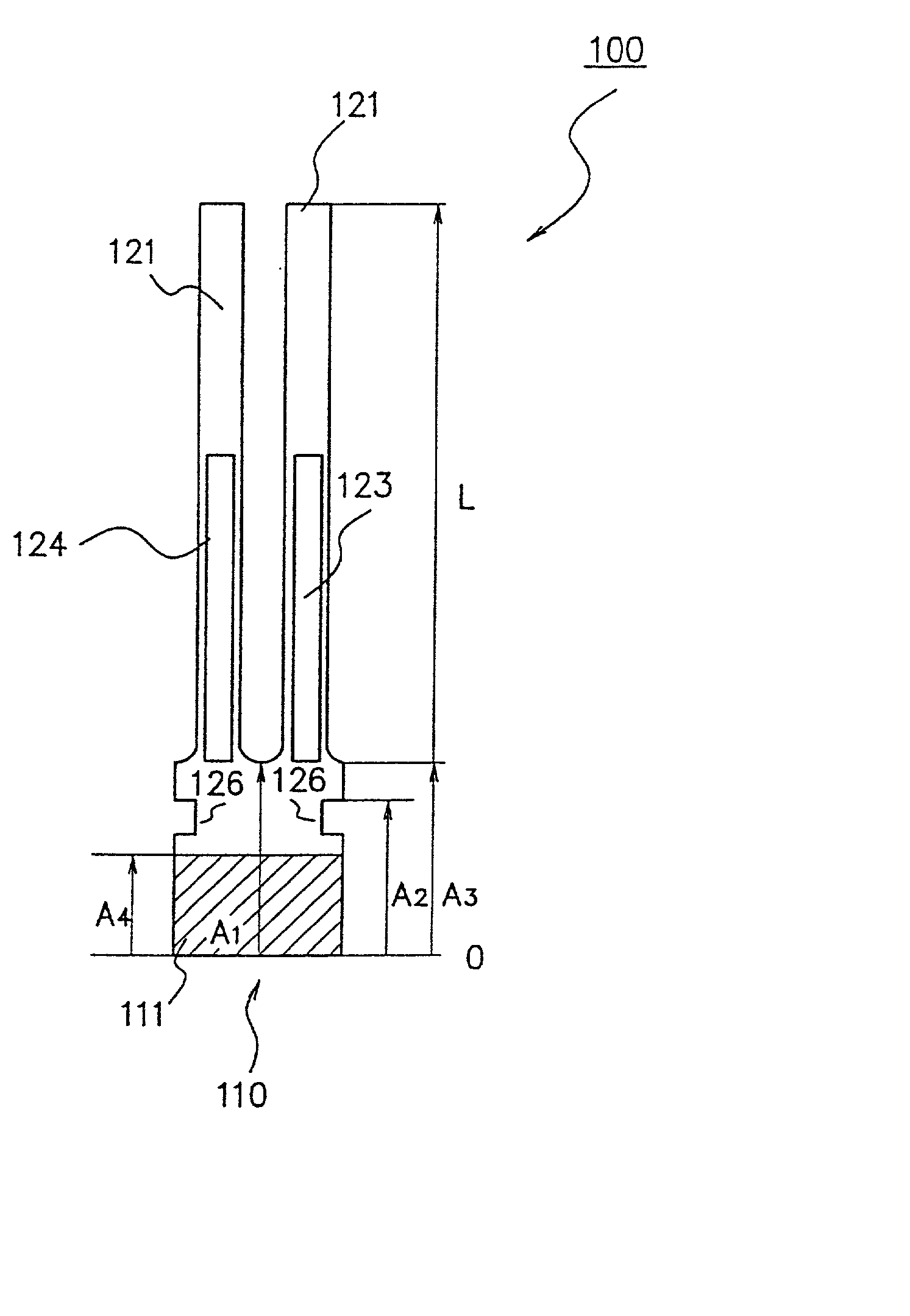
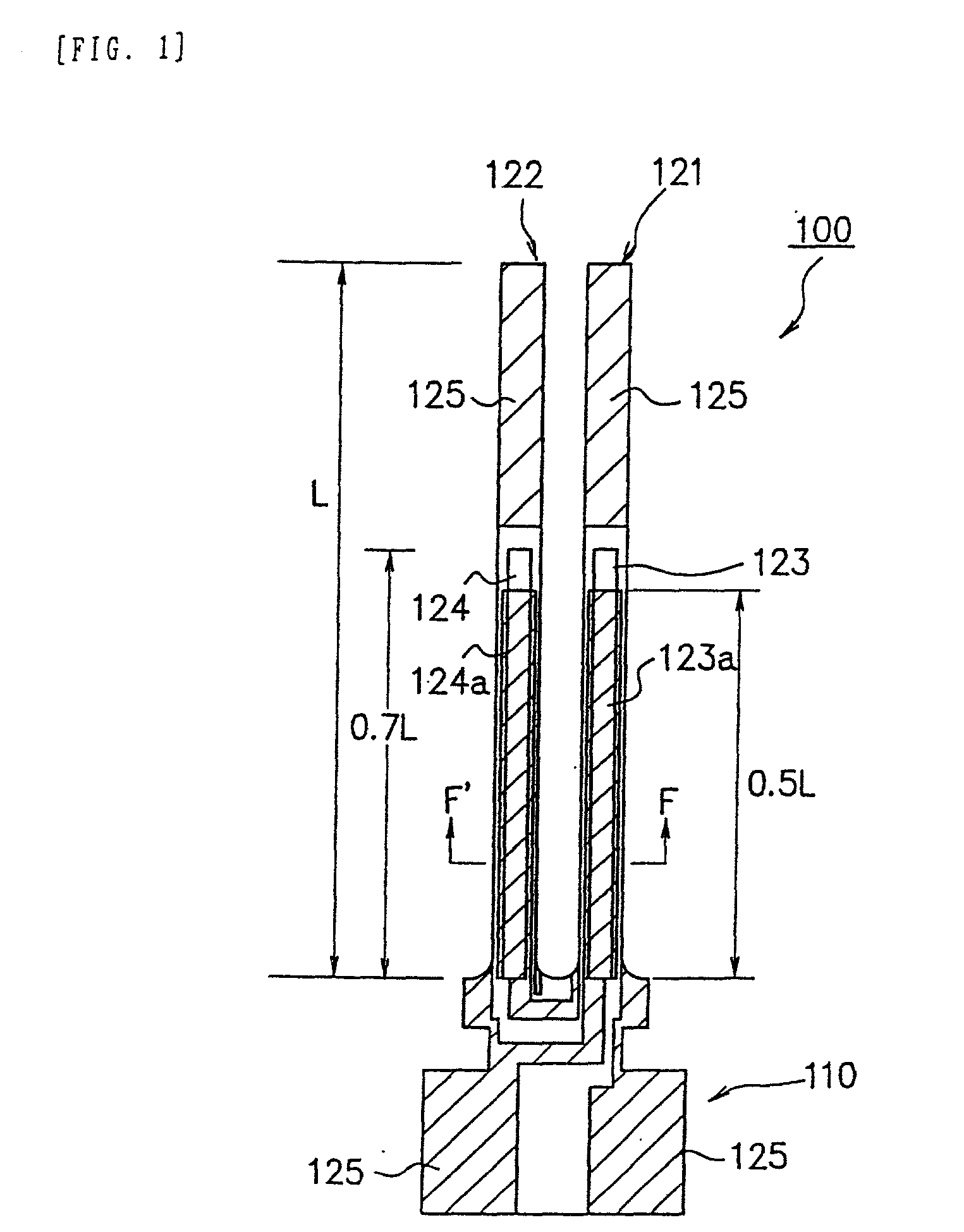
[0076] FIG. 1 shows a tuning-fork-type crystal vibrating piece 100 which is a vibrating piece according to the present invention.

[0077] The tuning-fork-type crystal vibrating piece 100 is formed in such a manner that a single quartz crystal is cut out so as to be formed as, for example, a commonly-called Z-plate crystal. Furthermore, since the tuning-fork-type crystal vibrating piece 100 shown in FIG. 1 is a vibrating piece which generates a signal at, for example, 32.768 kHz, it is formed to be very small.

[0078] Such a tuning-fork-type crystal vibrating piece 100, as shown in FIG. 1, has a base 110. Two tuning-fork arms 121 and 122, which are vibration arm sections, are arranged in such a manner as to protrude upward from the base 110 in the figure.

[0079] Furthermore, grooved portions 123 and 124 are formed on the obverse surfaces and the rear surfaces of the tuning-fork arms 121 and 122, as shown in FIG. 1. Similarly, since the grooved portions 123 and 124 are also formed on the r...

second embodiment

[0128] FIG. 7 shows a ceramic-packaged tuning-fork-type vibrator 200 which is a vibrator according to the present invention.

[0129] This ceramic-packaged tuning-fork-type vibrator 200 uses the tuning-fork-type crystal vibrating piece 100 of the above-described first embodiment. Accordingly, the same reference numerals are used for the construction, the operation, etc., of the tuning-fork-type crystal vibrating piece 100, and description thereof is omitted.

[0130] FIG. 7 is a schematic sectional view showing the construction of the ceramic-packaged tuning-fork-type vibrator 200. As shown in FIG. 7, the ceramic-packaged tuning-fork-type vibrator 200 has a box-shaped package 210 having a space therein.

[0131] This package 210 comprises a base 211 on the bottom thereof. This base 211 is formed by, for example, ceramic such as alumina.

[0132] A sealing section 212 is provided on the base 211, with the sealing section 212 being formed from the same material as that of the base 211. Furthermor...

third embodiment

[0135] FIG. 8 is a schematic view showing a portable digital phone 300 which is an electronic device according to the present invention.

[0136] This portable digital phone 300 uses the ceramic-packaged tuning-fork-type vibrator 200 of the above-described second embodiment and the tuning-fork-type crystal vibrating piece 100.

[0137] Accordingly, the same reference numerals are used for the construction, the operation, etc., of the ceramic-packaged tuning-fork-type vibrator 200 and the tuning-fork-type crystal vibrating piece 100, and description thereof is omitted.

[0138] FIG. 8 shows the circuit blocks of the portable digital phone 300. As shown in FIG. 8, in a case where transmission is performed by the portable digital phone 300, when the user inputs his / her voice into a microphone, the signal passes through pulse-width modulation / coding blocks, modulator / demodulator blocks, a transmitter, and an antenna switch, and is transmitted from an antenna.

[0139] On the other hand, a signal tr...


PUM


Abstract

A vibrating piece in which a CI values ratio is maintained constant while minimizing the CI value of the fundamental wave, variations of the CI values between the vibrating piece devices are reduced even if the base is made short, and the entire vibrating piece can be made smaller.

Description

FIELD OF THE INVENTION[0001] The present invention relates to a vibrating piece formed of, for example, a crystal, a vibrator having the vibrating piece, an oscillator having the vibrator, and an electronic device having the vibrator.DESCRIPTION OF THE RELATED ART[0002] Generally, a tuning-fork-type crystal vibrating piece is constructed as shown in, for example, FIG. 11.[0003] More specifically, a tuning-fork-type crystal vibrating piece 10 comprises a base 11, and two vibration arm sections 12 and 13 formed so as to protrude from the base 11. In these two arm sections 12 and 13, grooves 12a and 13a are formed on the obverse surface and the rear surface thereof, as shown in FIG. 12.[0004] FIG. 12 is a sectional view along the A-A' line in FIG. 11. As shown in FIG. 12, the vibration arm sections 12 and 13 are formed in such a manner that their cross section is formed in nearly an H shape from the grooves 12a and 13a.[0005] Furthermore, such grooves 12a and 13a are formed with excita...

Claims


Application Information

Patent Timeline
IPC IPC(8): H02N2/08H03H9/21
CPCH03H9/21
Inventor TANAYA, HIDEOKITAMURA, FUMITAKASAKATA, JUNICHIRO
Owner SEIKO EPSON CORP
Learn More