
Starter-generator device for internal combustion engines and method for operating the device

Inactive Publication Date: 2002-09-12
DAIMLER AG
View PDF12 Cites 10 Cited by
  • Summary
  • Abstract
  • Description
  • Claims
  • Application Information

AI Technical Summary

Benefits of technology

[0006] One particular advantage of the invention is that the flywheel generator can break away a combustion engine that has a considerably higher breakaway torque than the torque of the flywheel generator in the starting state with the flywheel generator stationary, in which it would also have to crank the engine from stationary. It is thus also possible to crank the engine from the stationary condition of the engine by means of the already rotating generator.
[0007] Another advantage is that the flywheel generator can be used to synchronize the gearbox. When changing up to a higher gear, the gearbox input shaft can be braked by the flywheel generator until the desired rotational speed has been reached.
[0008] Another advantage is that almost wear-free operation of the friction clutch between the flywheel generator and the combustion engine is possible because it can be assisted during the process of driving away by the action of the flywheel generator and, given appropriate dimensioning, can be closed almost without a speed difference.
[0009] In a preferred development of the invention, specifically in the passenger-car sector, a vehicle can drive either forwards or backwards in first gear, thus making it possible to omit the customary intermediate shaft for reverse gear in a customary change-speed gearbox. This represents a considerable simplification of the gearbox and weight savings in the drive train.
[0010] In another advantageous refinement, use is made of a gearbox in which a positive clutch is arranged on the input shaft. In interaction with the flywheel generator, this makes it possible to produce a particularly compact and inexpensive drive train.
[0011] Another advantage of the invention is that the flywheel generator can convert braking energy of the vehicle into other types of energy and thus serves as a wear-free brake.

Problems solved by technology

This has the disadvantage that the generator cannot be switched on to synchronize the gearbox in the state decoupled from the engine and the generator cannot start an engine with a high breakaway torque.

Method used


Image

  • Starter-generator device for internal combustion engines and method for operating the device
  • Starter-generator device for internal combustion engines and method for operating the device

Examples


Embodiment Construction

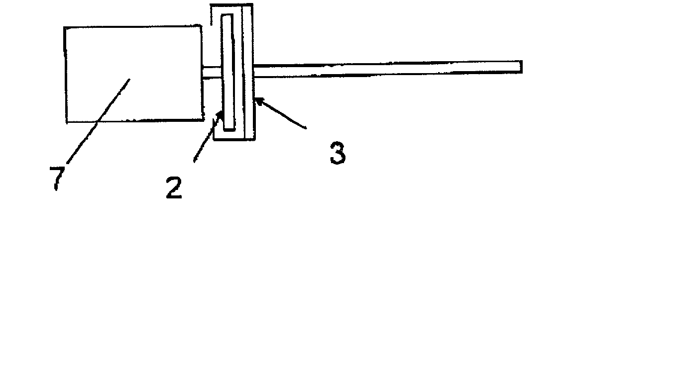
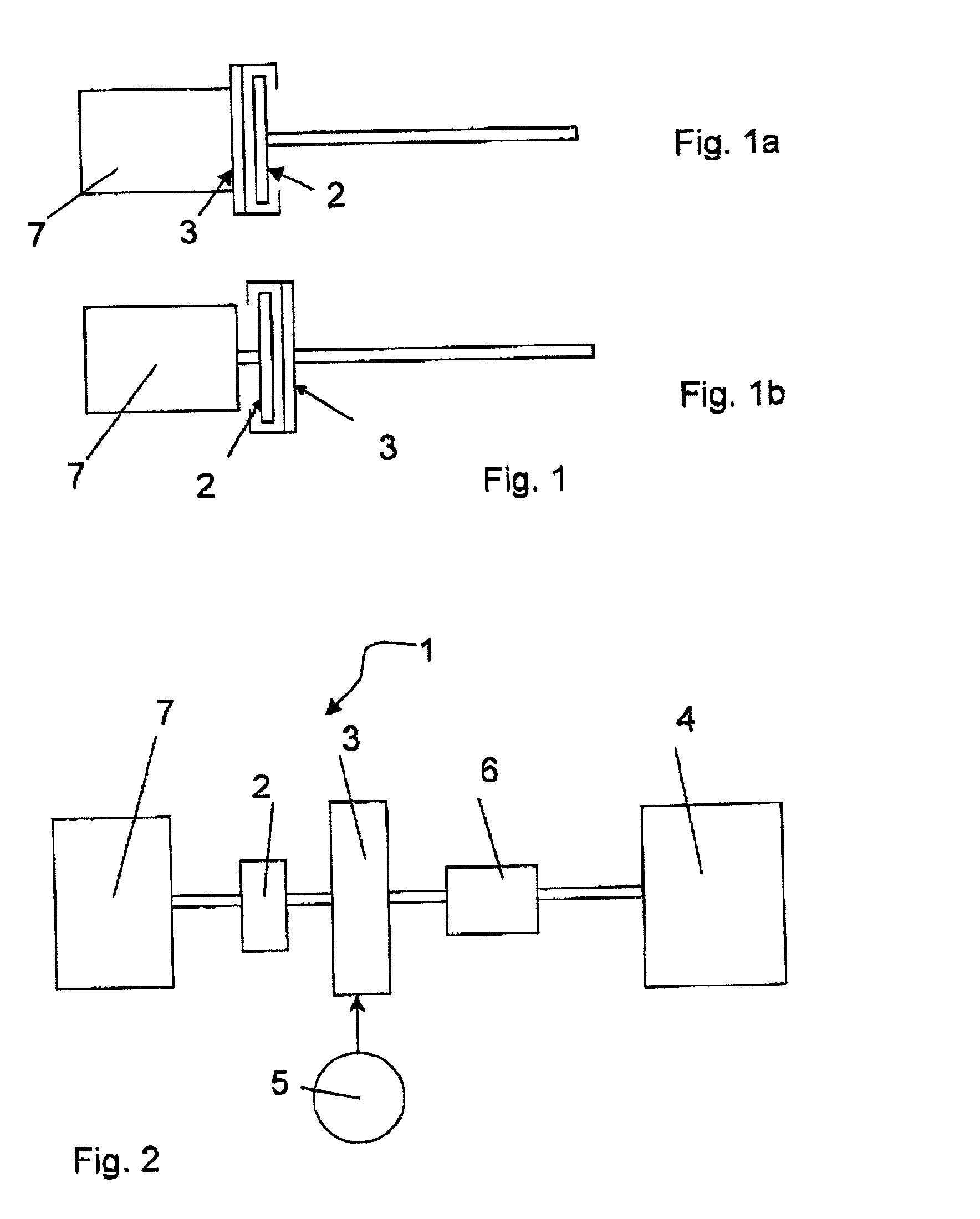
[0017] FIG. 1a gives a detail view of a conventional arrangement of a combustion engine 7 with its centrifugal mass 3 in accordance with the prior art. The centrifugal mass 3 is connected directly to the crankshaft of the combustion engine 7 and ensures that the combustion engine 7 operates with adequate smoothness. The centrifugal mass 3 can be decoupled from the remainder of the drive train by means of a friction clutch 2. To drive away, the engine is started and the friction clutch 2 is closed, for example, with the centrifugal mass 3 serving as a pressure plate for the friction clutch 2. FIG. 1b illustrates an arrangement in accordance with the invention. It is reversed compared with that in FIG. 1a, with the friction clutch 2 now being mounted between the crankshaft of the combustion engine 7 and the centrifugal mass 3, so that the centrifugal mass 3 of the combustion engine 7 can now be decoupled from the latter. Now that it is decoupled from the engine, the centrifugal mass c...


PUM


Abstract

A device with a starter-generator for internal combustion engines, the combustion engine having a centrifugal mass for stabilizing its smoothness of running, with at least one first nonpositive clutch and a flywheel generator, which can be actuated by means of an electrical energy source and is in effective connection with a selectable gearbox, the nonpositive clutch being provided between the flywheel generator, which can be actuated by means of an electrical energy source, and the combustion engine, and the flywheel generator forming the centrifugal mass of the combustion engine.

Description

BACKGROUND AND SUMMARY OF THE INVENTION[0001] This application claims the priority of German patent Document 100 47 755.0, filed Sep. 27, 2000, the disclosure of which is expressly incorporated by reference herein.[0002] The present invention relates to a starter-generator device for internal combustion engines and a method for operating the device.[0003] German Patent DE 19632074 C2 discloses a starting device for internal combustion engines with at least one first nonpositive clutch and a starter-generator that can be actuated by means of an electrical energy source and is in effective connection with a selectable gearbox. The nonpositive clutch is positioned after the flywheel generator and ahead of the gearbox. This has the disadvantage that the generator cannot be switched on to synchronize the gearbox in the state decoupled from the engine and the generator cannot start an engine with a high breakaway torque.[0004] An object of the invention is to design and arrange the starte...

Claims


Application Information

Patent Timeline
IPC IPC(8): F02N5/04F02N11/04F02N15/02
CPCF02N5/04F02N11/04F02N15/025
Inventor EBEL, PETERSCHWARZHAUPT, ANDREASSPIEGELBERG, GERNOTWILHELMI, VOLKERZUERN, JOERG
Owner DAIMLER AG
Features
  • Generate Ideas
  • Intellectual Property
  • Life Sciences
  • Materials
  • Tech Scout
  • Unparalleled Data Quality
  • Higher Quality Content
  • 60% Fewer Hallucinations
Learn More