Head-mounted image display device and data processing apparatus including the same

a display device and data processing technology, applied in the field of head-mounted image display devices and data processing apparatus including the same, can solve the problems of reducing work efficiency, limiting working space or hindering the designer from quickly finding required materials, and sometimes overlapping windows, so as to improve the portability and operability of the data processing apparatus, simplify the removal and mounting of the head-mounted image display, and facilitate the effect of handling

Inactive Publication Date: 2002-09-12
SEIKO EPSON CORP
View PDF11 Cites 76 Cited by
  • Summary
  • Abstract
  • Description
  • Claims
  • Application Information

AI Technical Summary

Benefits of technology

0069] With the above constitution, due to its integral structure in which image information from the portable arithmetic operation processing device is displayed on the head-mounted image display device, which is housed in the arithmetic optation processing device, this invention enables confidential documents to be prepared, eliminates a locational limitation in which the apparatus cannot be used unless the display is fully opened, and improves the portability and operability of the data processing apparatus. In addition, since the battery for driving the head-mounted image display device can be charged immediately after housing, and the arithmetic operation processing device and the head-mounted image display device communicate with each other by radio, the arithmetic operation processing device and the head-mounted image display device are completely separated from each other, thereby allowing the data processing apparatus to be handled easily in its use and significantly simplifying the removal and mounting of the head-mounted image display device in the housing section.

Problems solved by technology

In this case, the materials are scattered on and around the designer's desk, thereby limiting the working space or hindering the designer from finding required materials quickly.
This reduces the working efficiency.
If, however, a large number of parts are to be used and a large number of materials must be referenced at the same time, although several windows can be opened on the screen to display different materials in the different windows, the windows must sometimes overlap each other if a large number of windows must be used simultaneously due to the physically limited size and resolution of the CRT display for displaying information.
As a result, the amount of information that can be referenced at the same time is limited, and the efficiency provided by the introduction of CAE is thus limited; in some cases, it is faster to find required materials among those scattered on and around the table as described above.
The working efficiency is also reduced in the maintenance or repair of an installed apparatus, wherein the operator must carry out such an operation while referencing instruction manuals and wherein because the surroundings are in disorder, the operator cannot place the manuals in positions in which they can be referenced appropriately.
Under such conditions, however, it is further difficult to place a CRT display close to the operator, and the introduction of CAE is impossible.
Thus, no other appropriate solutions were available.
Published Unexamined Patent Application No. 5-100192 describes a method of displaying screens from electronics such as word processors on a spectacle-like display, but this is only a spectacle-shaped variation of conventional displays and is not suited to the presentation of a large number of materials.
Published Unexamined Patent Application No. 4-263283 proposes a portable virtual reality apparatus, but this simply provides an artificial reality apparatus and is not suited to the manipulation of displayed data.
In addition, for conventional head-mounted image display devices, several problems arising from the need to alternatively view a virtual image on the liquid crystal display and the corresponding image on the external keyboard due to the large difference in image quality between these images, have been pointed out.
Head-mounted image display devices of this type, however, also have problems.
For example, in such apparatuses, the visibility is very bad because external images are simply caused to overlap the corresponding display images, and alternatively viewing different images may strain the operator's eyes.
In this case, however, since data must be input while using a particular part of the field of view to check the input device, mounting the image display device on the operator's head eliminates the freedom of the operator's inputting position, and long time work thus results in a significant fatigue.
In addition, if a keyboard is used as an input device, the input operation is very difficult when the keys are larger than the tips of the operator's fingers, so the limit of the practical size of portable terminals depends on the size of the keyboard.
Furthermore, due to the fixed arrangement of keys in conventional keyboards, optimal key arrangements for various applications are not available.
Under these circumstances, the need of complicated procedures for creating motion pictures hinders people without expertise from providing adequate expressions using multiple media effectively.
For hypermedia applications, HyperCard commercially available from Apple Co., Ltd is popular, but requires a large number of mouse clicks, thereby possibly resulting in mistakes in clicking positions.
For movie postproduction processes for processing, synthesizing, and editing movie materials, a large amount of time is required to complete the process due to the need to accurately carry out complex procedures according to pre-calculations, and the flexibility of these processes is limited; it is impossible to test various combinations of images during the process.
In such conventional structures, the arithmetic operation device and the head-mounted image display device are always separated from each other, they must be carried separately, resulting in poor portability despite their reduced sizes.
Even if the head-mounted image display device is carried in an outer sheath case, handling becomes cumbersome, and faults are likely to occur.

Method used


Image

  • Head-mounted image display device and data processing apparatus including the same
  • Head-mounted image display device and data processing apparatus including the same
  • Head-mounted image display device and data processing apparatus including the same

Examples


embodiment 1

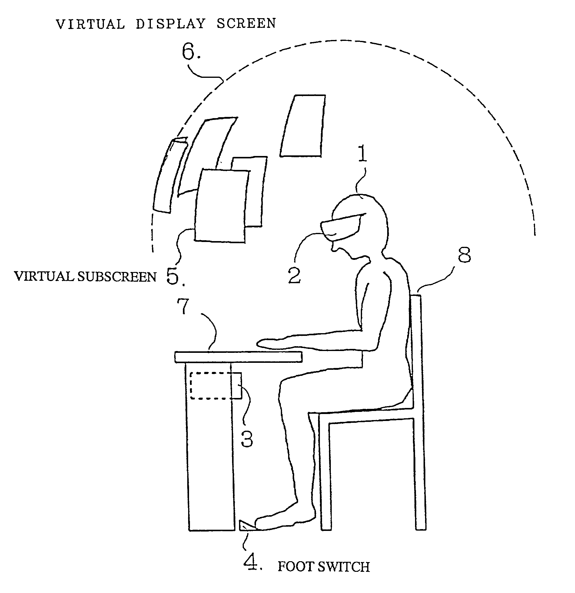
[0114] FIG. 1 shows an embodiment in which an operator 1 is sitting on a chair 8 to perform operation on a desk 7. The operator 1 has a head-mounted image display device 2 (hereafter referred to as a "display device") mounted on his or her head. A computer 3 is disposed under the desk 7 to transmit image display information to the display device 2 via a connection cord (see FIG. 2). Furthermore, the computer 3 has connected thereto a foot switch 4 that acts as a trigger input means.

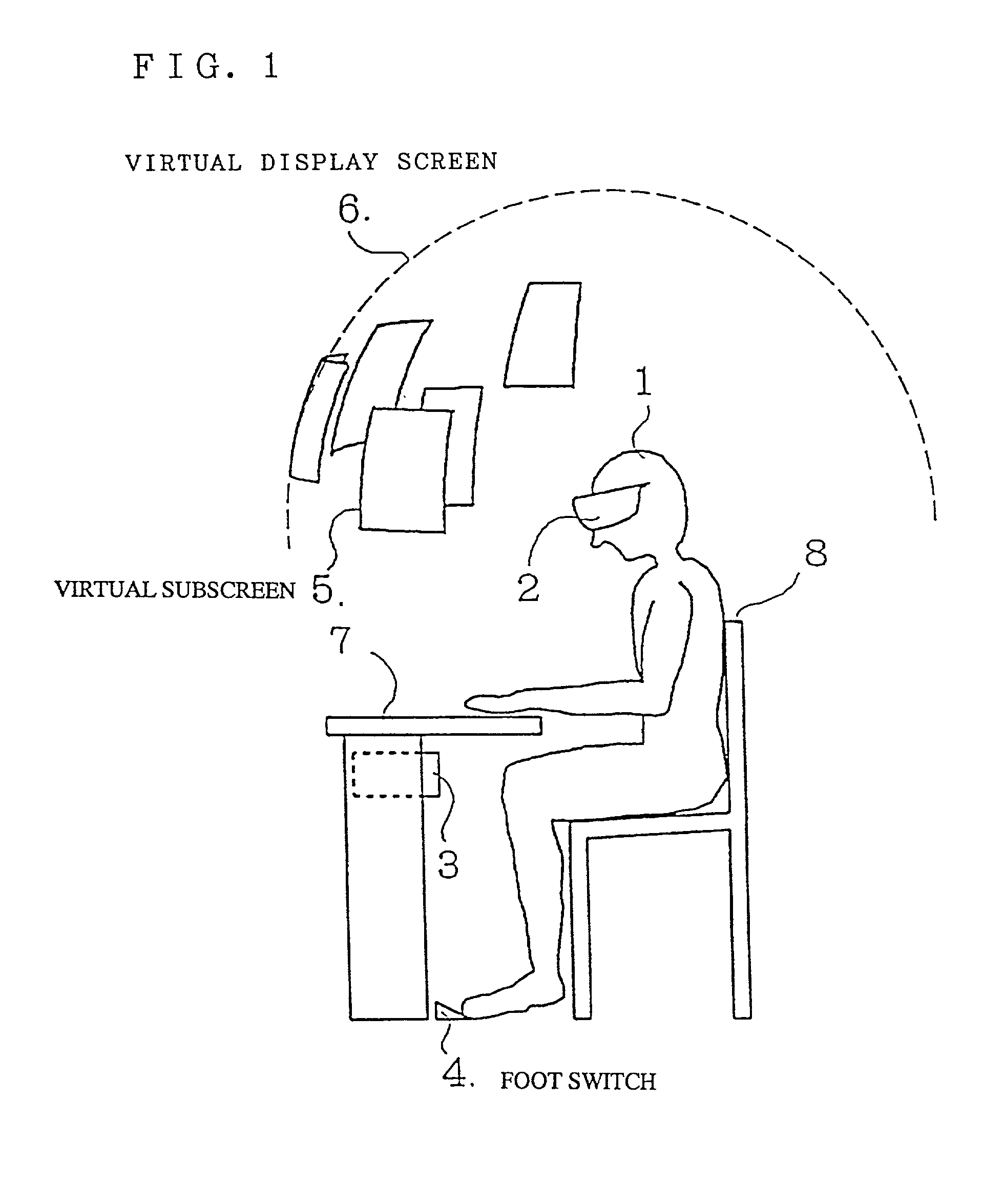
[0115] As shown in FIG. 2, the display device 2 has a spectacles-like frame 101 in which a drive circuit 105 is housed, and one end of the connection cord 106 is connected to the drive circuit 105. The drive circuit 105 and the computer 3 constitute an image generation means according to this invention. The frame 101 also has mounted in front thereof a liquid crystal panel 102 comprising a lateral pair of liquid crystal display devices and a back light 104 that illuminates the liquid crystal panel 102 rea...

embodiment 2

[0135] FIG. 8 shows an embodiment in which the operator 1 is repairing an apparatus 22. The display device 2 is mounted on the operator's head, and an angle sensor 21 is mounted on the operator's chest, and a portable computer 13 and a push switch that acts as a trigger input means are mounted on the operator's waist. The display device 2 is the same as in Embodiment 1, and its description is thus omitted. The display device 2 is connected to the computer 13 through a connection cord.

[0136] In looking somewhat upward, the operator 1 can view the display screen of a liquid crystal panel 102 as a virtual subscreen 5 on a virtual display screen 6, while in looking somewhat downward, the operator can view the apparatus 22 being repaired.

[0137] FIG. 9 shows a scene as seen by the operator 1. In this figure, both the entire virtual subscreen 5b and the lower part of a virtual subscreen 5c which are contained within the range shown by a display frame 51 corresponding to the maximum display...

embodiment 3

[0142] The display device 2 in the embodiment shown in FIG. 10 has a spectacles-like frame 101 including the liquid crystal panel 102, the enlarging lens 103, the back light 104, and a half mirror 135. The operator 1 can view an enlarged display image on the liquid crystal panel 102 and an external image (the keyboard) through optical paths 136 and 138, respectively. These images can be synthesized by the half mirror 135 and viewed by the operator 1. The operator 1 thus feels as if the liquid crystal display image were present outside the frame (near the keyboard), resulting in improved workability.

[0143] With this configuration, however, a few problems may occur. First, the liquid crystal display image and the external image simply overlap each other, so the display image cannot be distinguished clearly. Second, since the distance between the operator and the virtual image cannot be matched easily with the distance between the operator and the keyboard, focusing for eyes must be ca...


PUM


Abstract

A head-mounted image display device with a good operability and a data processing apparatus including such a display device. A head-mounted image display device wherein a liquid crystal panel and an enlarging optical system are crystal display panel through the enlarging optical system housed in a frame and wherein images generated on the liquid are visible in the field of view in front of the frame comprises a first direction detection means (107) disposed in part of the frame (101) for detecting the direction of the user's head; an observation point detection means (109) disposed in part of the frame for detecting the user's line of sight; a trigger input means (4) for transmitting trigger signals; and an image generation means (3, 105) for controlling images generated on the liquid crystal display panel based on signals from the first direction detection, observation point detection, and trigger input means.

Description

BACKGROUND OF THE INVENTION[0001] 1. Field of the Invention[0002] The present invention relates to a head-mounted image display device for displaying images on a screen showing a virtual space and to a data processing apparatus including this device.[0003] 2. Description of the Prior Art[0004] The design of electronic circuits or experiment thereon requires materials such as data sheets due to the need to confirm the specifications of parts to be used. In this case, the materials are scattered on and around the designer's desk, thereby limiting the working space or hindering the designer from finding required materials quickly. This reduces the working efficiency.[0005] To carry out design efficiently, computer aided engineering (CAE) for working out designs using computers has been introduced. That is, a paperless design environment has been established in which, for example, materials such as data sheets are registered in a computer to enable them to be displayed and referenced on...

Claims


Application Information

Patent Timeline
Patent Type & Authority Applications(United States)
IPC IPC(8): G02B27/00G02B27/01G06F1/16G06F3/00G06F3/01H04N5/64H04N5/74
CPCG02B27/017G02B27/0176G02B2027/0132G02B2027/014G02B2027/0141G02B2027/0156G02B2027/0187G02B2027/0198G06F1/1615G06F1/1616G06F1/163G06F1/1632G06F1/1637G06F1/1639G06F1/1654G06F1/1656G06F1/1684G06F3/011G06F3/013G06F3/014H04N5/64H04N5/7491
Inventor YASUKAWA, MASAAKIKINEBUCHI, TADASHIWATANABE, NORIKOYONENO, KUNIOUCHIYAMA, SYOICHIKAMAKURA, HIROSHIKARASAWA, JOJI
Owner SEIKO EPSON CORP
Why Eureka
Try Eureka