Recording-medium conveying device conveying a recording medium on a conveying belt charged with a positive charge and a negative charge alternately

a conveying device and recording medium technology, applied in the direction of thin material handling, printing, article delivery, etc., can solve the problems of enlarge the image-forming device as a whole, difficult color overlapping step, and increase the cos

Inactive Publication Date: 2002-09-12
RICOH KK
View PDF0 Cites 49 Cited by
  • Summary
  • Abstract
  • Description
  • Claims
  • Application Information

AI Technical Summary

Benefits of technology

0011] It is a general object of the present invention to provide an improved and useful recording-medium conveying device, a conveyance control device, and an inkjet recording device, in which the above-mentioned problems are eliminated.

Problems solved by technology

However, in performing this method, the step of overlapping the colors is difficult.
Further, the method involves complicated component devices including developing devices around the photosensitive member, which enlarges an image-forming device as a whole, and increases costs thereof.
However, applying the negative charge, as mentioned above, to the conveying belt in the vicinity of the recording head so as to lessen the electrostatic force necessitates a means therefor, which disadvantageously complicates an entire structure of a conveying device conveying the recording sheet.
Additionally, after an image is recorded on the recording sheet by jetting the ink drops thereon, separating the recording sheet from the conveying belt necessitates a separating force that exceeds the electrostatic force applied throughout the surface of the recording sheet, which makes it difficult to provide a separating unit capable of separating the recording sheet.
Further, when the conveying belt slips on the conveying roller, the recording sheet is displaced in a direction in which the recording sheet is conveyed by the conveying belt, reducing the precision of conveying the recording sheet.
When this cockling becomes aggravated, the recording sheet contacts the nozzles of the recording head, at worst, such that the nozzles of the recording head become dirty, and that the recording sheet is smeared.
Further, this cockling may displace the landing spots of the ink drops on the recording sheet.
However, pressing the recording sheet by the spur may leave a scar on the image formed on the recording sheet, resulting in a deterioration of the image.
However, when the recording sheet is vacuum-sucked by the recessing parts of the conveying belt so as to prevent the above-mentioned influences of the cockling of the recording sheet, the recording sheet in the vicinity of the recording head also becomes uneven according to the protruding parts and recessing parts formed on the surface of the conveying belt.
This unevenness on the recording sheet displaces the landing spots of the ink drops on the recording sheet, which results in a deteriorated image.
When an elevation of the recording sheet occurs in this state, the inkjet recording device is unable to deal with this elevation, and cannot secure a force for conveying the recording sheet; thereby, the precision of conveying the recording sheet cannot be guaranteed, and a quality of an image is reduced.

Method used


Image

  • Recording-medium conveying device conveying a recording medium on a conveying belt charged with a positive charge and a negative charge alternately
  • Recording-medium conveying device conveying a recording medium on a conveying belt charged with a positive charge and a negative charge alternately
  • Recording-medium conveying device conveying a recording medium on a conveying belt charged with a positive charge and a negative charge alternately

Examples


embodiments 1-4

[0130] [Embodiments 1-4]

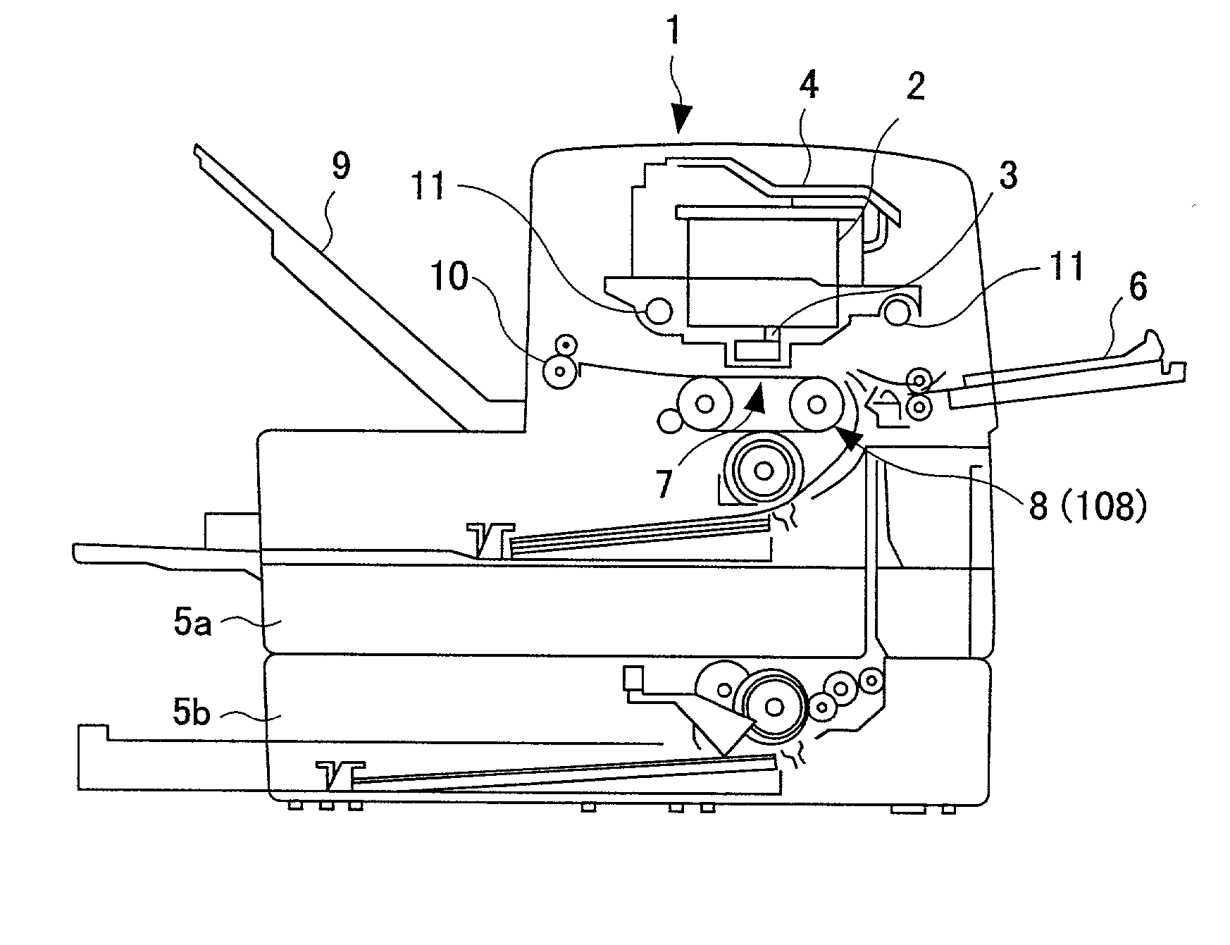
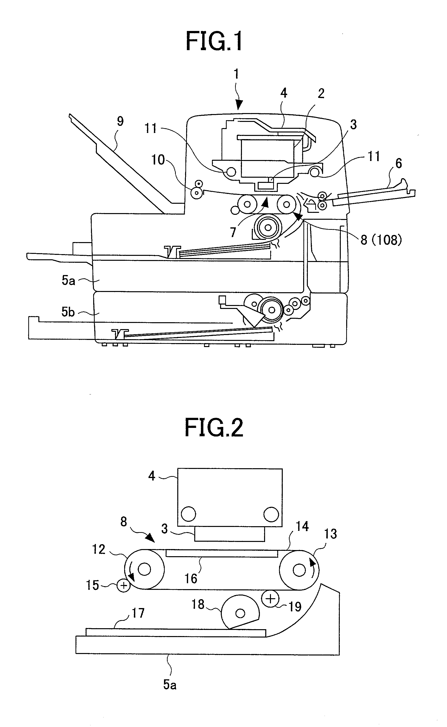
[0131] FIG. 1 is an illustration of a configuration of an inkjet printer according to a first embodiment of the present invention. As shown in FIG. 1, an inkjet printer 1 comprises four ink cartridges 2, four recording heads 3, a carriage 4, feeding trays 5a and 5b, a manual feeding tray 6, a recording-sheet conveying device 8, a delivery tray 9, and a delivery roller 10. The four ink cartridges 2 contain four inks of cyan C, magenta M, yellow Y, and black Bk, respectively. The four recording heads 3 have a plurality of nozzles, and are supplied with the inks from the four ink cartridges 2, respectively. The ink cartridges 2 and the recording heads 3 are mounted on the carriage 4. The feeding trays 5a and 5b contain recording sheets. The feeding trays 5a and 5b and the manual feeding tray 6 form a recording-medium feeding device. The recording-sheet conveying device 8 conveys a recording sheet from the feeding trays 5a, 5b, or the manual feeding tray 6 to a p...

embodiment 5

[0142] [Embodiment 5]

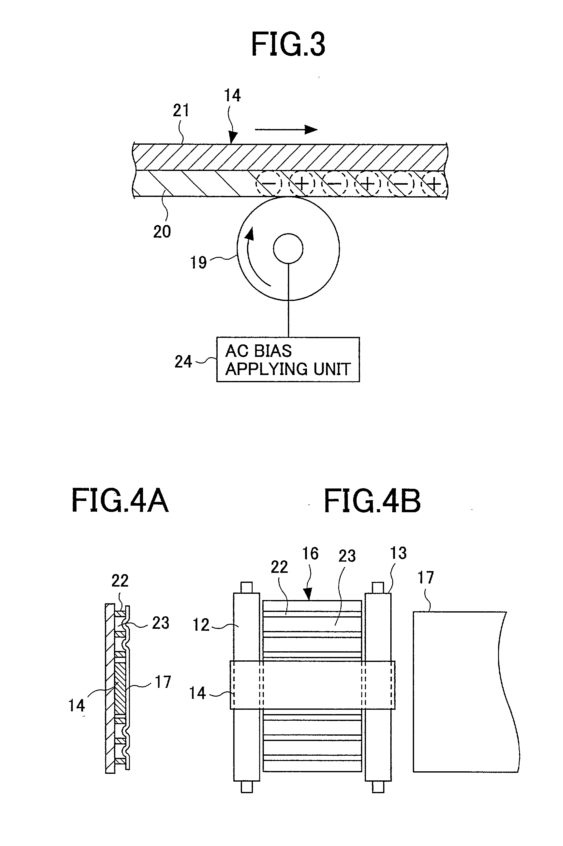
[0143] FIG. 13 is an illustration of a configuration of a recording-sheet conveying device according to a fifth embodiment of the present invention. As shown in FIG. 13, a recording-sheet conveying device 108 comprises a conveying belt 114, a belt charging roller (a belt charging unit) 115, a pressing roller 116, and a conveyance guide 117. The conveying belt 114 is wound around a driving roller 112 and a driven roller 113, and is capable of moving back and forth. The driving roller 112 is connected to a ground. A surface of the conveying belt 114 contacting the belt charging roller 115 is formed of an insulating layer. As shown in a sectional view of FIG. 14A and a top view of FIG. 14B, the conveying belt 114 is narrower than the recording sheet 17, and is wound around central parts of the driving roller 112 and the driven roller 113. The belt charging roller 115 is arranged opposite the driving roller 112 at a position upstream in a revolving direction of the ...

embodiment 6

[0151] [Embodiment 6]

[0152] FIG. 17 is an illustration of a configuration of an inkjet printer according to a six embodiment of the present invention. As shown in FIG. 17, an inkjet printer 201 of a serial type comprises four ink cartridges 202, a recording head 203, a carriage 204, feeding trays 205a and 205b, a manual feeding tray 206, a recording-sheet conveying device 208, a delivery tray 209, and a delivery roller 210. The four ink cartridges 202 contain four inks of cyan C, magenta M, yellow Y, and black Bk, respectively. The recording head 203 has a plurality of nozzles, and are supplied with the inks from the four ink cartridges 202, respectively. The ink cartridges 202 and the recording head 203 are mounted on the carriage 204. The feeding trays 205a and 205b contain recording sheets. The feeding trays 205a and 205b and the manual feeding tray 206 form a recording-medium feeding device. The recording-sheet conveying device 208 conveys a recording sheet from the feeding tray...


PUM


Abstract

This recording-medium conveying device comprises a conveying belt, the conveying belt, a belt charging unit, and a pressing roller. The conveying belt is wound around a driving roller and a driven roller so as to convey a recording medium to an image recording part. The conveying belt includes an insulating layer formed at one side contacting the recording medium. The belt charging unit is provided in contact with the insulating layer so as to charge the insulating layer with a positive charge and a negative charge alternately in a moving direction of the conveying belt by applying an AC bias to the conveying belt. The pressing roller presses the conveying belt against the driving roller so as to prevent the conveying belt from slipping on the driving roller.

Description

BACKGROUND OF THE INVENTION[0001] 1. Field of the Invention[0002] The present invention generally relates to a conveying device conveying a recording medium, such as a recording sheet, on which an image is printed by jetting a liquid such as an ink thereto, a conveyance control device, and an inkjet recording device printing such an image on the recording medium, and more particularly, to a conveying device which can convey the recording medium with high precision so as to increase a positional precision of applying the liquid onto the recording medium to stably form a high-quality image on the recording medium.[0003] 2. Description of the Related Art[0004] A full-colored image can be formed by an electrophotographic method including steps of forming an electrostatic latent image on a photosensitive member, developing each color, and then overlapping the developed colors. However, in performing this method, the step of overlapping the colors is difficult. Further, the method involve...

Claims


Application Information

Patent Timeline
Patent Type & Authority Applications(United States)
IPC IPC(8): B41J2/01B41J11/00B41J11/02B41J11/06B41J11/42B41J13/08B41J13/10B65H5/00B65H5/02B65H7/14
CPCB41J11/007B41J11/06B41J11/42
Inventor MAKI, TSUNEOBANNAI, KAZUNORI
Owner RICOH KK
Why Eureka
Try Eureka