
Toner cleaning device, image forming method using the device, and image forming apparatus using the device

a cleaning device and toner technology, applied in the field of toner cleaning device, image forming method using the device, image forming apparatus using the device, can solve the problems of difficult to completely remove the residual toner on the photoreceptor, mechanical weakness of the organic photoreceptor, degradation as well as abrasion, etc., to achieve excellent cleaning performance, excellent electrophotographic image, and no image defects

Inactive Publication Date: 2002-09-12
KONICA CORP
View PDF0 Cites 17 Cited by
  • Summary
  • Abstract
  • Description
  • Claims
  • Application Information

AI Technical Summary

Benefits of technology

[0013] A first object of the present invention is to provide a toner cleaning device which solves the aforesaid problems, is capable of maintaining excellent cleaning performance, resulting in no image defects, and forming excellent electrophotographic images for an extended period of time, when an organic photoreceptor as well as a polymerization toner is employed; an image forming method using the toner cleaning device; and an image forming apparatus using the toner cleaning device.
[0014] A second object of the present invention is to provide a toner cleaning device which solves the aforesaid problems and minimizes insufficient cleaning, which tends to occur in a toner cleaning device which is constituted in a manner such that the cleaning blade is provided just above the cylindrical organic photoreceptor (hereinafter referred to as a cylindrical photoreceptor, an organic photoreceptor, or simply a photoreceptor), maintains excellent cleaning performance, results in no image defects, and forms excellent electrophotographic images for an extended period of time when a polymerization toner is employed; an image forming method using the toner cleaning device; and an image forming apparatus using the toner cleaning device.
[0015] The inventors of the present invention conducted intensive investigations to solve the aforesaid problems. As a result, it has become possible to assure excellent cleaning properties as well as to maintain stabilized vibration of the cleaning blade (hereinafter occasionally referred to as the blade) by adhering a damping martial onto the cleaning blade or its supporting member, whereby it has become possible to overcome the problems. Namely, it was discovered that the first object of the present invention was achieved by employing any of the structures described below.
[0026] Further, in the toner cleaning device which is structured in such a manner that a cleaning blade is provided just above the cylindrical organic photoreceptor, it has become possible to assure excellent cleaning properties as well as to produce excellent electrophotographic images over an extended period of time. Namely, it was discovered that the second object of the present invention was achieved employing any of the structures described below.

Problems solved by technology

However, organic photoreceptors are mechanically weak.
Due to that, problems occur in which, during copying or printing a large number of sheets, the photoreceptor surface tends to result in degradation as well as abrasion.
As a result, after transferring the toner image to a transfer material in the transfer process, it is difficult to completely remove the residual toner which remains on the photoreceptor.
Accordingly, during cleaning of the photoreceptor surface, various problems tend to occur.
Thus, when a conventional cleaning blade is employed for cleaning, cleaning problems tend to occur, in which the blade is subjected to curl-under, whereby a toner is not completely removed due to vibrational fluctuation of the blade.
However, in the vibration damping technique described herein, vibration is damped employing a vibration damping means which is also employed as the blade holding member linearly joined to the blade.
Accordingly, the vibration of the blade itself is not sufficiently damped.
At the same time, it is difficult to achieve a stable enough connection due to the small joined area between the blade and the holding member.
Therefore, blade vibration tends to become unstable.
However, the toner so prepared, employing the production processes, exhibits a limit in make the particle size distribution uniform.
Accordingly, the toner results in insufficient particle size distribution as well as insufficient uniformity of particle shape.
As a result, in the electrophotographic images prepared employing the pulverized toner, it is difficult to sufficiently achieve high image quality.
When the polymerization toner is used in an image forming apparatus, employing the organic photoreceptor, new technical problems occur.
As is well known, spherically shaped toner particles, which remain on the organic photoreceptor, tend to result in insufficient cleaning.
Specifically, the surface of the organic photoreceptor tends to result in abrasion.
When toner particles are adhered onto roughened surfaces formed through the abrasion, fine toner particles, which do not affect image formation, are not removed over an extended period of time and stain charging members (such as a charging wire and a charging roller), so that halftone images result in image unevenness.
However, these proposals have not sufficiently overcome the problems.
However, the image forming apparatus tends to result in insufficient cleaning due to the following reason.
As a result, toner particles scraped by the cleaning blade tend not to leave the photoreceptor surface resulting often in cleaning failure.
Specifically, when the polymerization toner is applied to an image forming apparatus which is constituted in a manner such that the toner cleaning device is provided just above the cylindrical organic photoreceptor, fine toner particles, which do not affect image formation, are not removed over an extended period of time and therefore stain charging members (such as the charging wire and the charging roller), whereby halftone images result in image unevenness.

Method used


Image

  • Toner cleaning device, image forming method using the device, and image forming apparatus using the device
  • Toner cleaning device, image forming method using the device, and image forming apparatus using the device
  • Toner cleaning device, image forming method using the device, and image forming apparatus using the device

Examples


example 1

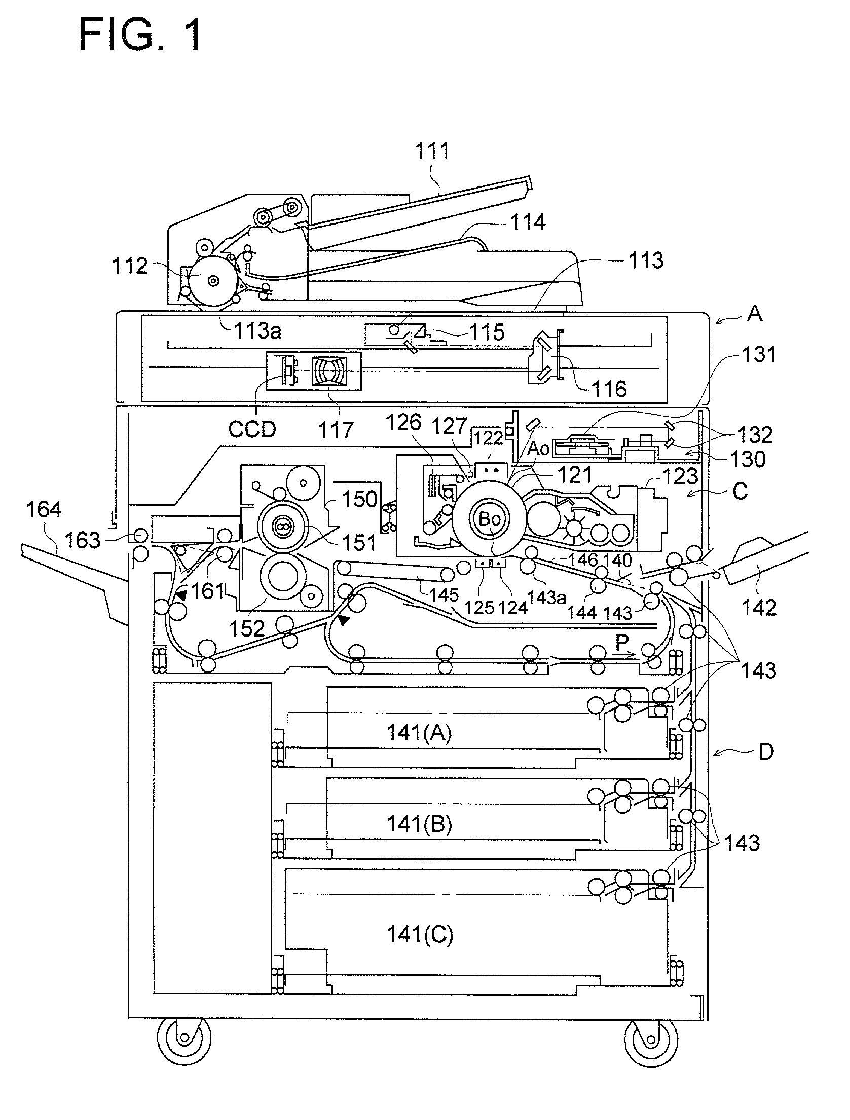
[0261] Insufficient residual toner removal, blade curl-under, blade noise, and image unevenness were evaluated employing a digital copier, Konica 7050, manufactured by Konica Corp., basically comprising the image forming process (including processes of corona charging, laser exposure, reversal development, electrostatic transfer, claw separation, and cleaning utilizing a cleaning blade) described in FIG. 1, in which the joined state of the cleaning blade with the supporting member, the damping material adhesion position, the blade contact load, and the contact angle combinations were set as shown in Table 2. During the evaluation, an original document, having equal quarters of a text image at a pixel ratio of 7 percent, a gray scale image, a solid white image, and a solid black image, was continuously copied onto A4 paper sheets for 90 minutes at a rate of 50 sheets / minute at normal temperature and normal humidity (24.degree. C. and 60 percent relative humidity). However, prior to t...

example 2

[0299] Evaluation was carried out in the same manner as Example 1, except that conditions of the cleaning blade, the damping material, the photoreceptor, the developer, and the like were varied as described below.

[0300] Cleaning blade: hardness of 70 degrees, impact resilience of 50 percent, thickness of 2.5 mm, and free length of 5 mm

[0301] Damping material: Scotch Damp SJ2015X-Type 112 (manufactured by Sumitomo 3M Limited.) (having a maximum loss factor .eta..sub.max of approximately 1.0)

[0302] Photoreceptor: P2

[0303] Developer: 2 (Toner: T2)

[0304] Other cleaning conditions are:

[0305] Cleaning blade contact angle: described in Table 3

[0306] Cleaning blade load (in N / m): described in Table 3

[0307] Other conditions were same as Example 1.

[0308] Table 3 shows the results.

3 TABLE 3 2A 2B 2C 2D 2E 2F 2G Joined in in in in in in in State of para- para- para- para- para- para- series Cleaning llel llel llel llel llel llel Blade with Supporting Member Damping present present present prese...

example 3

[0310] Evaluation was carried out under the same conditions as Example 1, except that the photoreceptor and the developer were replaced with those described below and the type of the damping material were was varied as shown in Table 4.

[0311] Photoreceptor: P2

[0312] Developer: 2 (Toner: T2)

4 TABLE 4 3A 3B 3C Joined State of in parallel in parallel in parallel Cleaning Blade with Supporting Member Damping Material present present present Adhesion Section FIG. 3 (a) FIG. 3 (a) FIG. 3 (a) Type of LR-A VEM 113 LR-V Damping manufactured by manufactured by manufactured Material Bridgestone Sumitomo 3M by Bridgestone Corp. Limited Corp. S.sub.1 (in mm.sup.2) 3060 3060 1850 S.sub.2 (in mm.sup.2) 6120 6120 6120 S.sub.1 / S.sub.2 0.5 0.5 0.5 Cleaning Blade 20 20 20 Load (in N / m) Cleaning Blade 15 15 20 Contact Angle .theta. (in degrees) Insufficient A A A Residual Toner Removal Blade Curl-Under A A A Vibration 130 130 140 Amplitude (in .mu.m)

[0313] As can clearly be seen from Table 4, Examples ...


PUM


Abstract

An image forming method comprising: the steps of developing an electronic latent image formed on an organic photoreceptor with a developer containing a toner; transferring a toner image formed by the developing on the photoreceptor onto a transfer material; and then removing toner which remains on the organic photoconductor employing a toner cleaner device comprising a cleaning blade, a supporting member of the cleaning blade, and a damping material. The cleaning blade and the supporting member are partially joined in parallel to each other, and the damping material is adhered onto either the cleaning blade or the supporting member.

Description

BACKGROUND OF THE INVENTION[0001] The present invention relates to a toner cleaning device employed in electrophotographic copiers and printers, an image forming method using the toner cleaning device, and an image forming apparatus using the toner cleaning device.[0002] In recent years, as image holding bodies, employed in electrophotographic image forming apparatus, organic photoreceptors (hereinafter referred simply to as photoreceptors) comprising organic photoconductive materials have been most widely employed. Organic photoreceptors are superior to other photoreceptors since it is easier to develop materials in response to various types of exposure light sources ranging from visible light to infrared light; it is possible to select materials which result in no environmental pollution; the production cost is lower; and the like. However, organic photoreceptors are mechanically weak. Due to that, problems occur in which, during copying or printing a large number of sheets, the p...

Claims


Application Information

Patent Timeline
IPC IPC(8): G03G21/00
CPCG03G21/0029
Inventor SATO, KAZUHIKOUCHINO, SATOSHIMOCHIZUKI, FUMITAKAENDO, ISAO
Owner KONICA CORP
Learn More