Fuel cell generation system and method

a fuel cell and generation system technology, applied in the direction of fuel cells, fuel cell grouping, fuel cell details, etc., can solve the problems of reducing the efficiency of the fuel cell generation system, the possibility of an explosion cannot be completely denied, etc., to achieve high efficiency, reduce electric power required, and secure the effect of safety

Inactive Publication Date: 2002-09-12
PANASONIC CORP
View PDF4 Cites 17 Cited by
  • Summary
  • Abstract
  • Description
  • Claims
  • Application Information

AI Technical Summary

Benefits of technology

0012] An object of the present invention, in consideration of such problems described above, is to provide a fuel cell generation system which secures its safety with a possibility of an explosion or abnormal combustion eliminated and reduces electric power required for the ventilation to maintain its high efficiency.

Problems solved by technology

In addition, a possibility of an explosion cannot be completely denied if the worst happens.
Thus the problem associated with this example is that the increased electric power consumption leads to a reduction in efficiency of the fuel cell generation system.

Method used


Image

  • Fuel cell generation system and method
  • Fuel cell generation system and method
  • Fuel cell generation system and method

Examples


embodiment 1

[0054] (Embodiment 1)

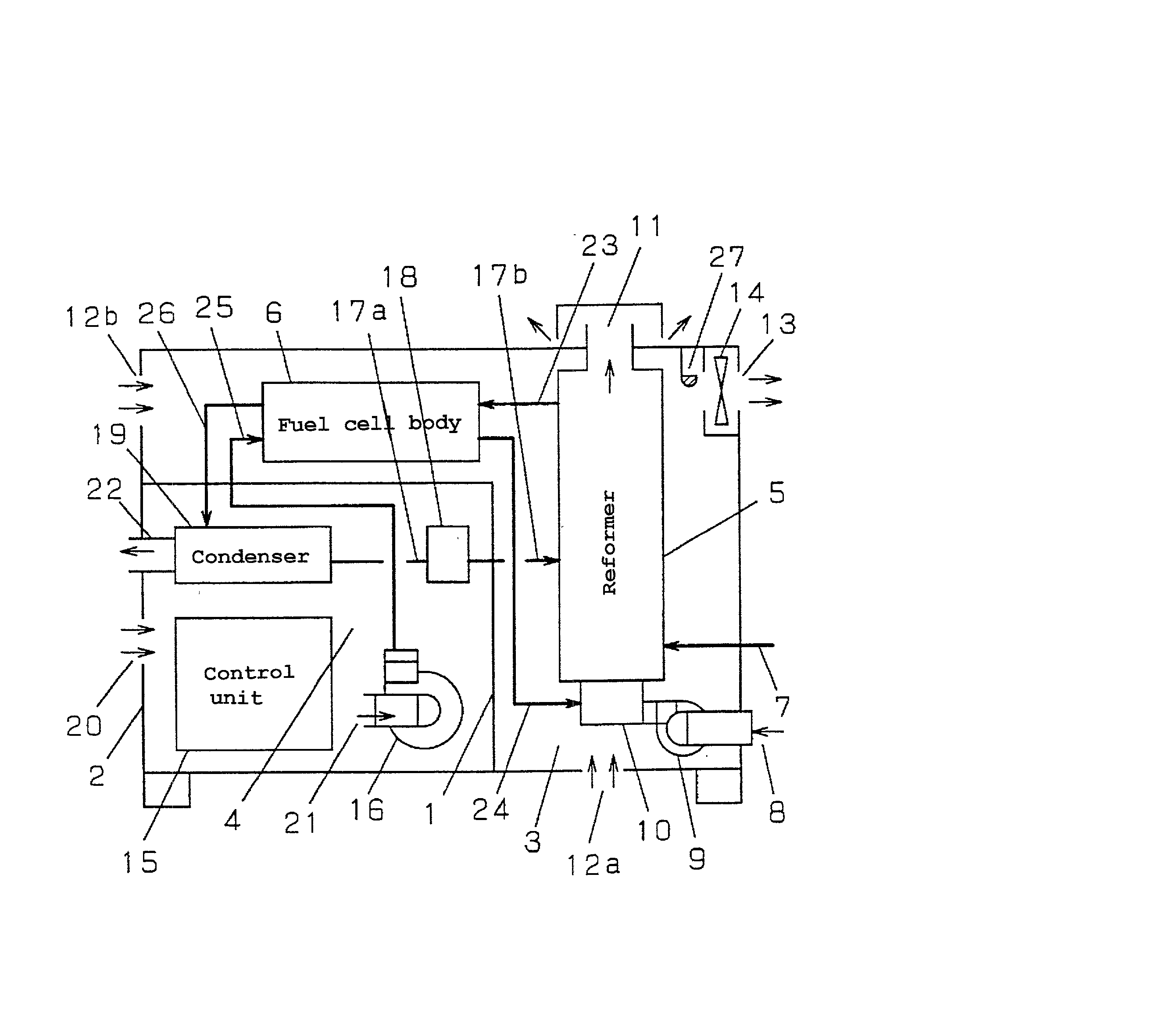
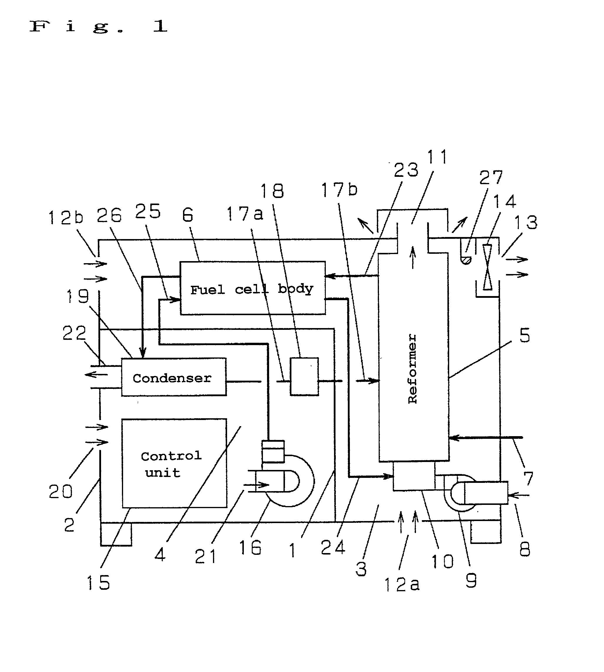
[0055] FIG. 1 is a block diagram showing a fuel cell generation system according to Embodiment 1 of the present invention.

[0056] In FIG. 1, reference numeral 1 denotes a partition wall for partitioning an interior of a package 2 into a gas path compartment 3 and a non gas compartment 4. Components through which flammable gases flow such as a reformer 5 and a fuel cell body 6 are positioned in a gas path compartment 3.

[0057] The reformer 5 is provided with raw material gas piping 7, a burner 10 fitted with a combustion inlet 8 and a combustion fan 9, and a reformer outlet 11. A predetermined part of the frame member of the package 2 which constitutes outer walls of the gas path compartment 3 is provided with gas path compartment inlets 12a, 12b, a gas path compartment outlet 13, and a ventilation fan 14.

[0058] Components such as a control unit 15, an air blower 16, and a condenser 19 connected through water piping 17a to a water supplying apparatus 18 are positio...

embodiment 2

[0073] (Embodiment 2)

[0074] Embodiment 2 according to the present invention will now be described with reference to FIG. 1, as in the case of Embodiment 1.

[0075] This embodiment has basically the same configuration as Embodiment 1, so that this paragraph will describe the following matters in more detail.

[0076] This paragraph will omit the descriptions of the matters which have already been described in Embodiment 1.

[0077] In Embodiment 2, the gas path compartment outlet 13 is provided with the ventilation fan 14 and the gas path compartment inlets 12a and 12b are provided sufficiently away from the gas path compartment outlet 13. Specifically, as shown in FIG. 1, the gas path compartment inlets 12a and 12b are provided for the outer walls of package 2 at the underside of the reformer 5 and at the lateral position of the fuel cell body 6 respectively. That is, the reformer 5 and the fuel cell body 6 are placed between the gas path compartment outlet 13 (corresponding to an outlet fo...

embodiment 3

[0080] (Embodiment 3)

[0081] Embodiment 3 according to the present invention will now be described with reference to FIG. 1, as in the case of Embodiments 1 and 2.

[0082] This embodiment has basically the same configuration as the above described embodiment, so that this paragraph will describe the following matters in more detail.

[0083] This paragraph will omit the descriptions of the matters which have already been described in the above mentioned embodiments.

[0084] In embodiment 3, the combustion fan inlet 8 which supplies air for the combustion to the burner 10 of the reformer 5 and the reformer outlet 11 for discharging the combustion gas open into an exterior of the package 2.

[0085] Opening the combustion fan inlet 8 into the exterior of the package 2, even in the event that the flammable gas leaks out of a flammable gas flowing component, the leaked flammable gas never flows into the burner 10 from the combustion fan inlet 8. So that an explosion or abnormal combustion can be p...


PUM

PropertyMeasurementUnit
flammableaaaaaaaaaa
electric poweraaaaaaaaaa
temperatureaaaaaaaaaa

Abstract

In accordance with a fuel cell generation system of the present invention, an interior of a package 2 is partitioned into a gas path compartment 3 and a non gas compartment 4 with a partition wall 1, a component through which flammable gas flows is placed within the gas path compartment 3, a part of the frame member of the package 2 constituting the gas path compartment 3 is provided with gas path compartment inlets 12a and 12b, a gas path compartment outlet 13 and a ventilation fan 14, a component through which the flammable gas does not flows is placed within the non gas compartment 4, and a part of the frame member of the package 2 of the non gas compartment 4 is provided with a non gas compartment inlet 20, allowing a blower inlet 21 to open into an interior of the non gas compartment 4 and allowing an air outlet 22 to open into an exterior of the package 2.

Description

BACKGROUND OF THE INVENTION[0001] 1. Field of the Invention[0002] The present invention relates to a fuel cell generation system in which a fuel cell for generating electric power by reacting hydrogen with oxygen is installed with in a package.[0003] 2. Related Art of the Invention[0004] A conventional fuel cell generation system is disclosed in Japanese Patent Laid-Open No.5-290868 and Japanese Patent Laid-Open No. 4-75263, for example.[0005] The entire disclosure of these Japanese Patent Laid-Open No. 5-290868 and Japanese Patent Laid-Open No. 4-75263 is incorporated herein by reference in its entirety.[0006] FIG. 2 shows a configuration from Japanese Patent Laid-Open No. 5-290868 as Conventional Example 1. In FIG. 2, reference numeral 51 denotes a package whose interior is partitioned into an electric apparatus compartment 53 and a high temperature apparatus compartment 54 with a partition wall 52. A control unit 55 is installed within the electric apparatus compartment 53, while...

Claims


Application Information

Patent Timeline
Patent Type & Authority Applications(United States)
IPC IPC(8): H01M8/04H01M8/06H01M8/24
CPCH01M8/00H01M8/0625H01M8/247Y02E60/50H01M8/02H01M8/24
Inventor UEDA, TETSUYAMIYAUCHI, SHINJINAKAMURA, AKINARI
Owner PANASONIC CORP
Why Eureka
Try Eureka