Transceiver for fixed wireless access network applications

a wireless access network and receiver technology, applied in wireless communication services, electrical equipment, wireless communication services, etc., can solve the problems of increasing the cost of coaxial cable installation, and increasing so as to facilitate the management of transceiver functions, reduce the cost of wireless network installation, and improve the reliability of the system

Inactive Publication Date: 2002-09-12
DRAGONWAVE
View PDF13 Cites 260 Cited by
  • Summary
  • Abstract
  • Description
  • Claims
  • Application Information

AI Technical Summary

Benefits of technology

0010] Advantageously, this arrangement provides a single wireless access network unit, which may be conveniently mounted on the outside of a building, and which receives wireless radio signals (for example in the microwave frequency range) and converts the incoming signals to a form which can be transmitted over a local communications link, e.g. the internal wiring of the building, to the appropriate user digital device or customer data processing unit(s). The single unit can therefore reduce the cost of a wireless network installation as compared to the conventional approach which employs at least one outdoor mounted radio transceiver and at least one indoor network termination unit. Advantageously, the single combined wireless radio transceiver and signal conversion unit can be adapted to connect directly to existing in-building wiring, thereby obviating the need for new wiring which adds to the installation costs.
0011] In a preferred embodiment, the unit includes management means to manage functions of the radio transceiver section. Advantageously, the proximity of the signal conversion section to the radio transceiver section facilitates management of transceiver functions in comparison to the prior art arrangement in which management of the outdoor transceiver unit by the indoor network termination unit would be limited or precluded altogether due to the data and protocol traffic density imposed on the coaxial cables carrying communications between the two. Moreover, the single unit approach of the present invention improves reliability of the system due to the reduced complexity and number of components of the equipment required as compared to the conventional approach.

Problems solved by technology

One drawback of this conventional arrangement is that the wireless network equipment requires new indoor wiring 7, 12, 14 to be installed between the ORT and the NTU and between the NTU and the computer terminals.
Coaxial cable is expensive and difficult to install and therefore costly to the customer.
A disadvantage of this conventional installation is that it requires one or more secure fitted equipment rooms for the indoor network termination units, together with one or more power supply systems for providing power to the indoor units.

Method used


Image

  • Transceiver for fixed wireless access network applications
  • Transceiver for fixed wireless access network applications
  • Transceiver for fixed wireless access network applications

Examples


Embodiment Construction

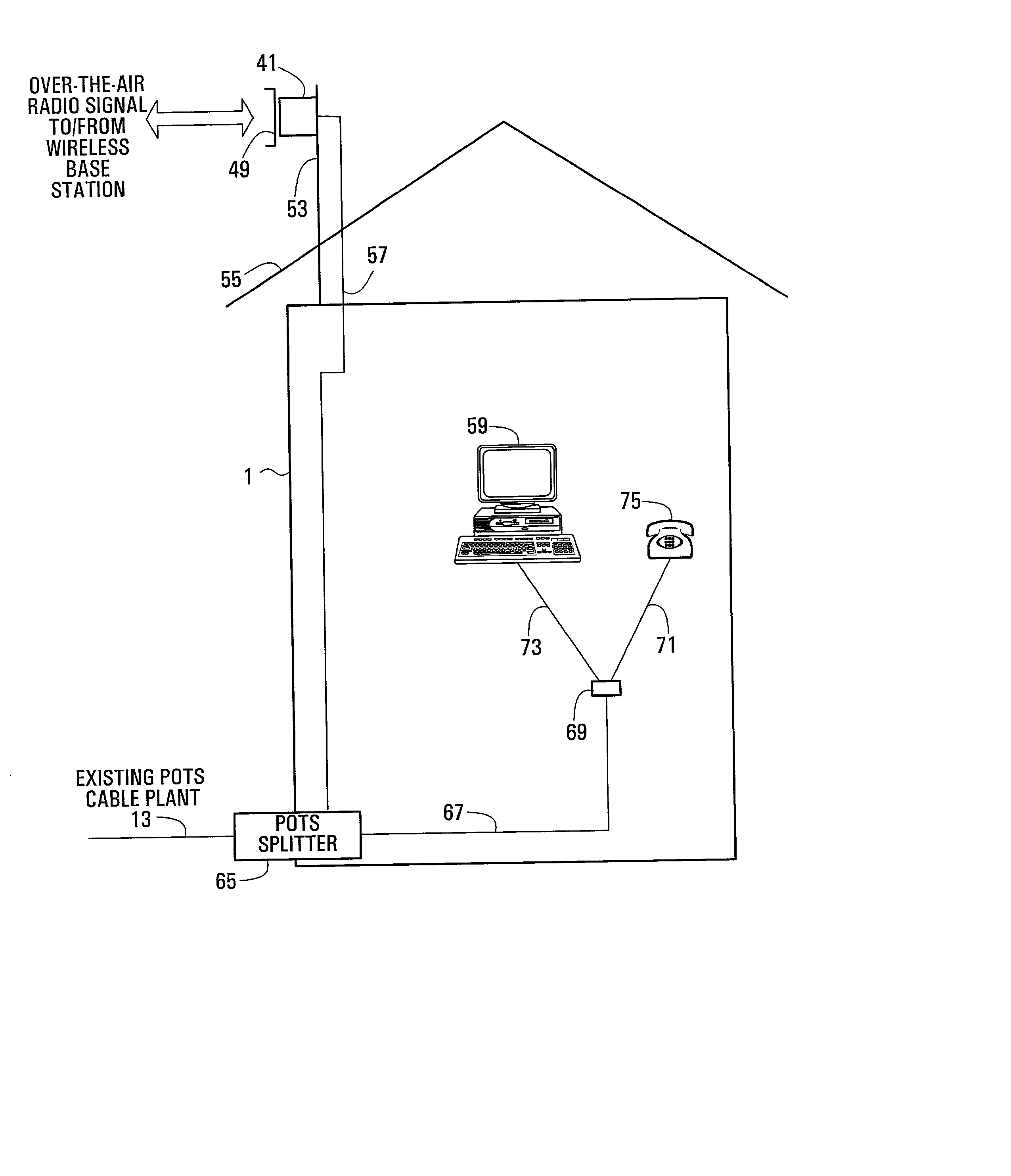
[0025] FIG. 3 shows a communication signal conversion unit according to one embodiment of the present invention. Referring to FIG. 3, the unit 41 comprises a microwave transceiver 43, an intermediate circuit and baseband radio modem 45 and a digital network interface 47. The microwave transceiver 43 receives microwave communication signals via the microwave antenna 49 and includes a down-converter (not shown) for down-converting the received microwave frequency signal to an intermediate frequency signal which is then passed to the IF circuit and baseband radio modem 45. The microwave transceiver 43 also includes an up-converter (not shown) for up-converting intermediate frequency communication signals generated by the IF circuit and baseband radio modem 45 to microwave frequencies for wireless transmission by the microwave antenna 49. The IF circuit and baseband radio modem 45 includes a demodulator (not shown) for demodulating the IF signal received from the microwave transceiver 4...


PUM


Abstract

A combined wireless transceiver and signal conversion unit comprises a radio receiver for receiving a wireless radio signal, and a converter for converting the signal into a form having a communications protocol supported by a communications port of a user digital device. An output device is provided for transmitting the converted signal to a user digital device via a wireline or other suitable medium for carrying the converted signal. The unit includes an input device for receiving a communications signal from the communication port of a user digital device via a wireline or other suitable signal transmission medium, and a transmitter for converting the received signal to a form for wireless transmission.

Description

FIELD OF THE INVENTION[0001] The present invention relates to a transmitter and receiver for fixed wireless access network applications and in particular but not limited to local multi-point distribution service (LMDS) and multi-channel multi-point distribution service (MMDS) networks.BACKGROUND OF THE INVENTION[0002] Wireless communication networks are being deployed to provide digital two-way voice, data, internet and video services to subscribers located within cities, suburban areas and remote areas as an alternative to wireline communication services. Examples of multi-point wireless access systems include local-multi-point distribution service (LMDS) which typically operates at frequencies of between 24 to 31 GHz and 37 to 42 GHz and multi-channel multi-point distribution service (MMDS), which typically operates at frequencies in the range of 2.1 to 7 GHz. These wireless access systems employ fixed, sectorized base stations or central offices which receive communication servic...

Claims


Application Information

Patent Timeline
Patent Type & Authority Applications(United States)
IPC IPC(8): H04W88/02
CPCH04W88/021
Inventor BOCH, ERIKDUXBURY, TOM ALEXANDER
Owner DRAGONWAVE
Why Eureka
Try Eureka