Hermetically sealed feedthrough connector using shape memory alloy for implantable medical device

a technology of shape memory alloy and feedthrough connector, which is applied in the field of hermetically sealed feedthrough connector using shape memory alloy for implantable medical devices, feedthrough connector assembly, etc., to achieve the effect of reducing the number of components and low leakage ra

Inactive Publication Date: 2002-09-12
PACESETTER INC
View PDF0 Cites 38 Cited by
  • Summary
  • Abstract
  • Description
  • Claims
  • Application Information

AI Technical Summary

Benefits of technology

0022] Yet another feature of the present invention is the provision of such a feedthrough connector which employs a reduced number of components when compared with known feedthrough connector constructions.
0023] Still a further feature of the present invention is the provision of such a feedthrough connector using a shape memory alloy which requires only simple installation tooling, is performed at relatively low temperatures, results in a finished product which exhibits a low leakage rate, and allows sealing of dissimilar materials, such as titanium and non-methodized ceramic base.

Problems solved by technology

Problems which arise in the construction and use of multiple conductor lead connectors are primarily related to the design of the electrical interconnection between the conductors and the contacts.

Method used


Image

  • Hermetically sealed feedthrough connector using shape memory alloy for implantable medical device
  • Hermetically sealed feedthrough connector using shape memory alloy for implantable medical device
  • Hermetically sealed feedthrough connector using shape memory alloy for implantable medical device

Examples


Embodiment Construction

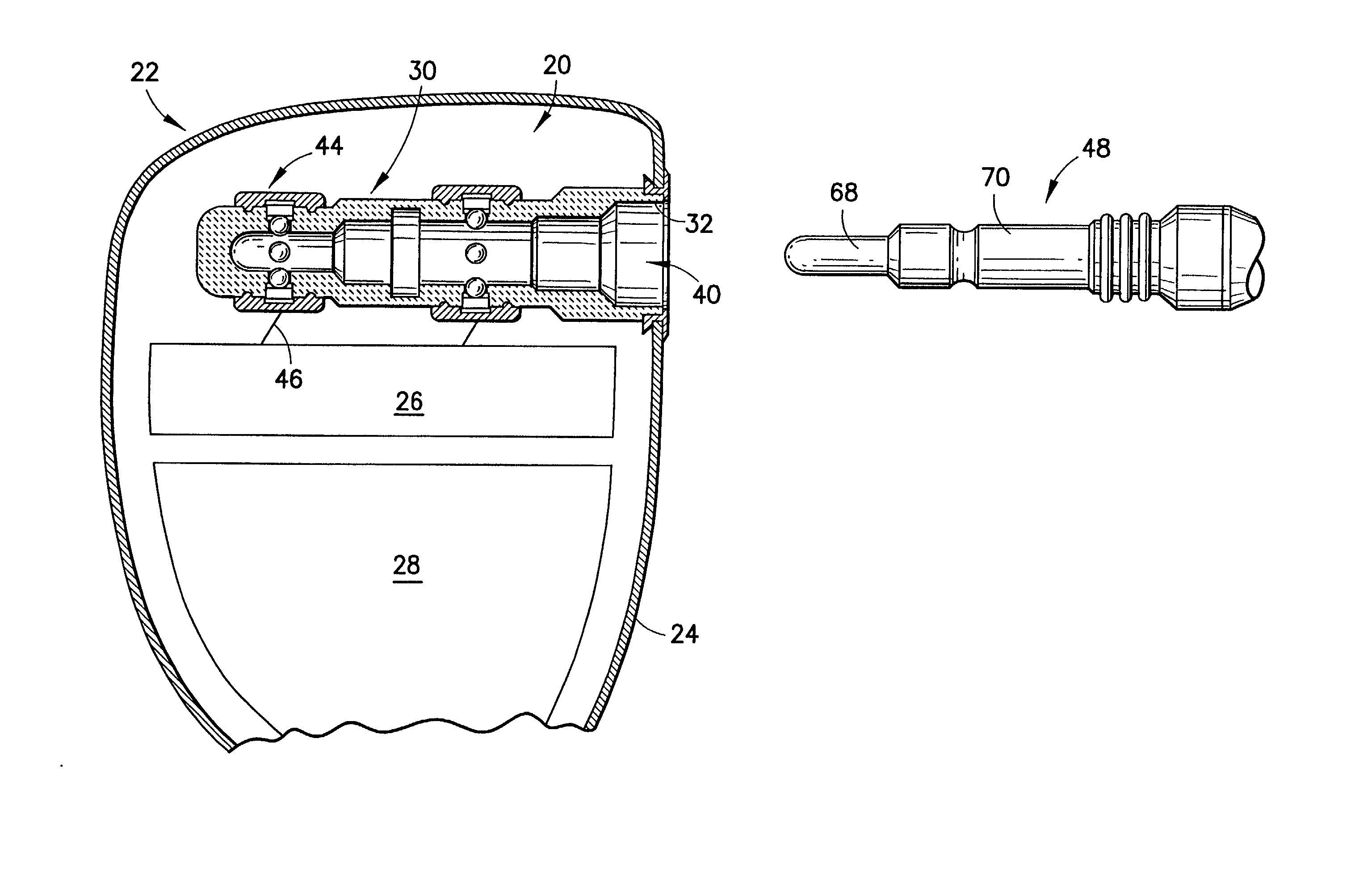
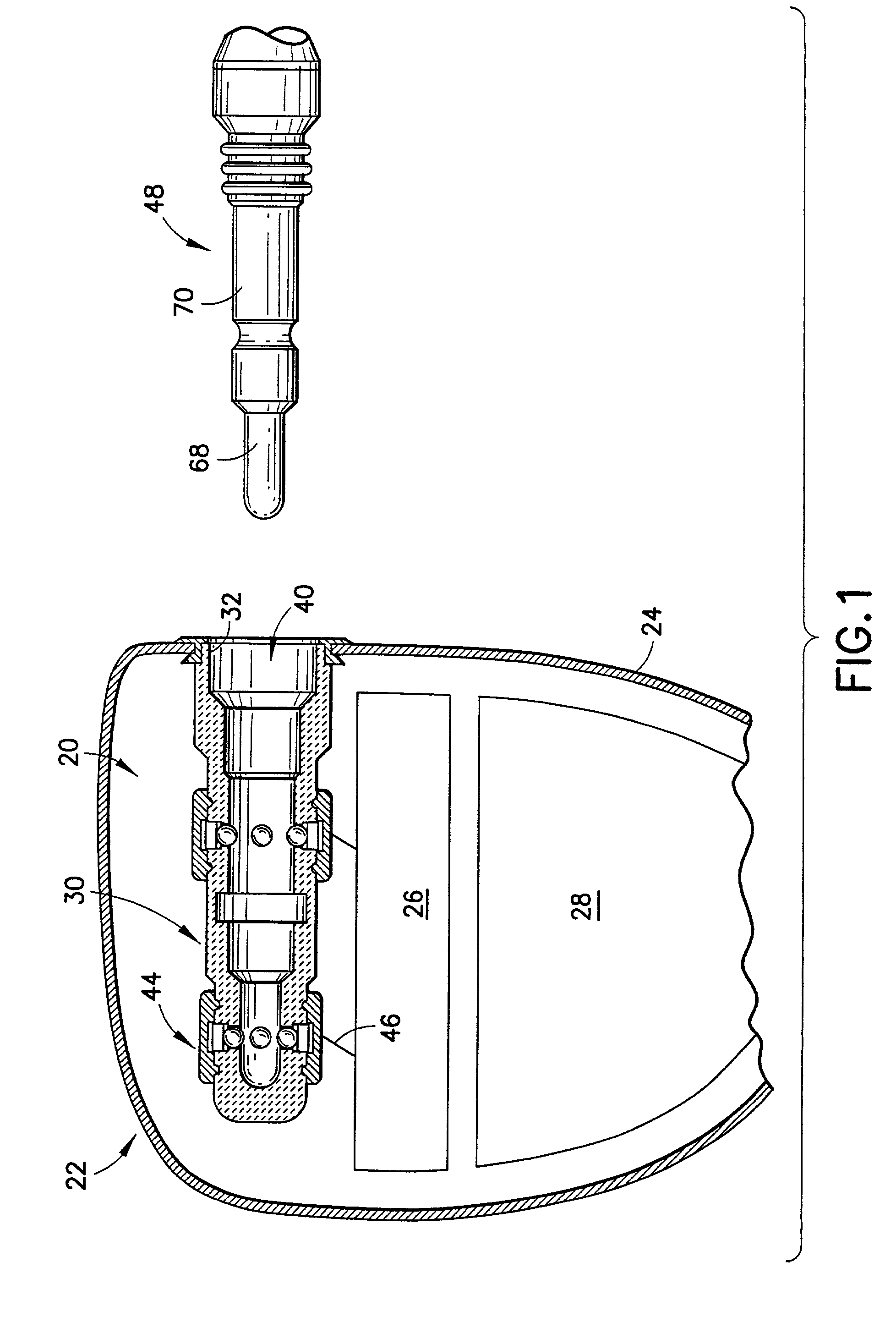
[0032] Turn now to the drawings and, initially to FIG. 1 which generally illustrates a feedthrough connector 20 for an implantable medical device 22, such as a pacemaker, including a hermetically sealed housing 24 and an electrical circuit 26 within the housing powered by a suitable battery 28. Although the present invention will be described with reference to the embodiments shown in the drawings, it should be understood that the present invention can be embodied in many alternate forms or embodiments. In addition, any suitable size, shape or type of elements or materials may be used.

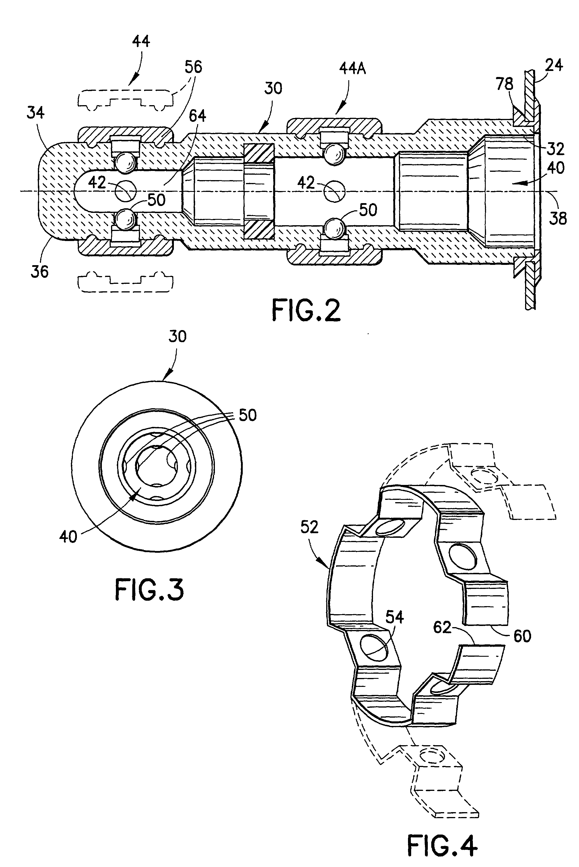
[0033] As best seen in FIGS. 2 and 3, the feedthrough connector 20 includes a tubular barrel 30 having an open end 32, a closed end 34, an outer peripheral surface 36, a longitudinally extending tubular barrel axis 38 passing through the open end and the closed end. The tubular barrel 30 defines a tubular channel 40 that protrudes into the sealed housing while maintaining the seal of the housing. The i...


PUM


Abstract

A feedthrough connector for an implantable medical device includes a hermetically sealed housing containing an electrical circuit and a tubular barrel with an open end and a closed end defining a tubular channel that protrudes into the sealed housing while maintaining the seal of the housing. The inside of the tubular channel is open to the outside of the sealed housing through the open end and the tubular barrel also has a plurality of circumferentially spaced openings extending between an outer peripheral surface and the tubular channel. An electrical contact assembly electrically in common with the electrical circuit within the housing serves to make electrical contact with an electrical lead axially inserted into the open end of the tubular channel. The electrical contact assembly includes a plurality of contact members received in and projecting radially through a plurality of circumferentially spaced openings and a sleeve member of shape memory alloy freely overlies the contact members when in a first deformed-shape configuration but engage the contact members and the outer peripheral surface of the tubular barrel when in a second memory-shaped configuration, urging the contact members into mechanical, electrical, and hermetically sealed engagement with the electrical lead. The tubular channel may include a plurality of conductive cylindrical portions coaxial with the axis of the tubular barrel, the dimensions of the diameter of the successive cylindrical portions progressively decreasing from the open end to the closed end.

Description

FIELD OF THE INVENTION[0001] The present invention relates generally to an electrical connector used with an implantable medical device, such as a pacemaker, for stimulating selected body tissue for connecting an implantable electrical lead to the electrical circuits within a hermetically sealed housing of the medical device. More particularly, the present invention relates to a feedthrough connector assembly which employs shape memory alloy components for ease of manufacture and for assuring a hermetically sealed engagement with the electrical lead.BACKGROUND OF THE INVENTION[0002] Implantable electronic devices are in use providing electronic pulses to stimulate tissue via a lead extending from an implanted pulse generator to a desired internal location. An example of this type of technology is a pacemaker and a pacing lead which provides electrical stimulation to the heart. The pacemaker is usually implanted in a subcutaneous cavity, and the leads extend either transvenously to t...

Claims


Application Information

Patent Timeline
Patent Type & Authority Applications(United States)
IPC IPC(8): A61N1/375
CPCA61N1/3752
Inventor IMANI, RAYNASON, CLYDE K.
Owner PACESETTER INC
Why Eureka
Try Eureka