Architecture for built-in self-test of parallel optical transceivers

a technology of optical transceivers and built-in self-testing, which is applied in the direction of electronic circuit testing, measurement devices, instruments, etc., can solve the problems of not being able to handle the electrical interface of dc-coupled transceivers, existing test equipment, and reducing manufacturing yields

Inactive Publication Date: 2002-09-12
IBM CORP
View PDF0 Cites 11 Cited by
  • Summary
  • Abstract
  • Description
  • Claims
  • Application Information

AI Technical Summary

Problems solved by technology

However, reliable manufacture and low-cost testing of parallel transceivers pose a number of problems, and manufacturing yields can be reduced significantly due to increased complexity in both chip and module construction.
Since testing equipment for parallel transceivers are generally unavailable, utilizing conventional testing equipment and method designed for testing serial transceivers multiplies the testing time when applied to parallel transceivers.
Furthermore, existing test equipment are not designed to handle the electrical interface of DC-coupled transceivers.
Also, present limitations of the opto-electronic components also require that full-rate testing of a parallel optical transceiver does not rely on transmission of a full-rate clock signal.

Method used


Image

  • Architecture for built-in self-test of parallel optical transceivers
  • Architecture for built-in self-test of parallel optical transceivers
  • Architecture for built-in self-test of parallel optical transceivers

Examples


Embodiment Construction

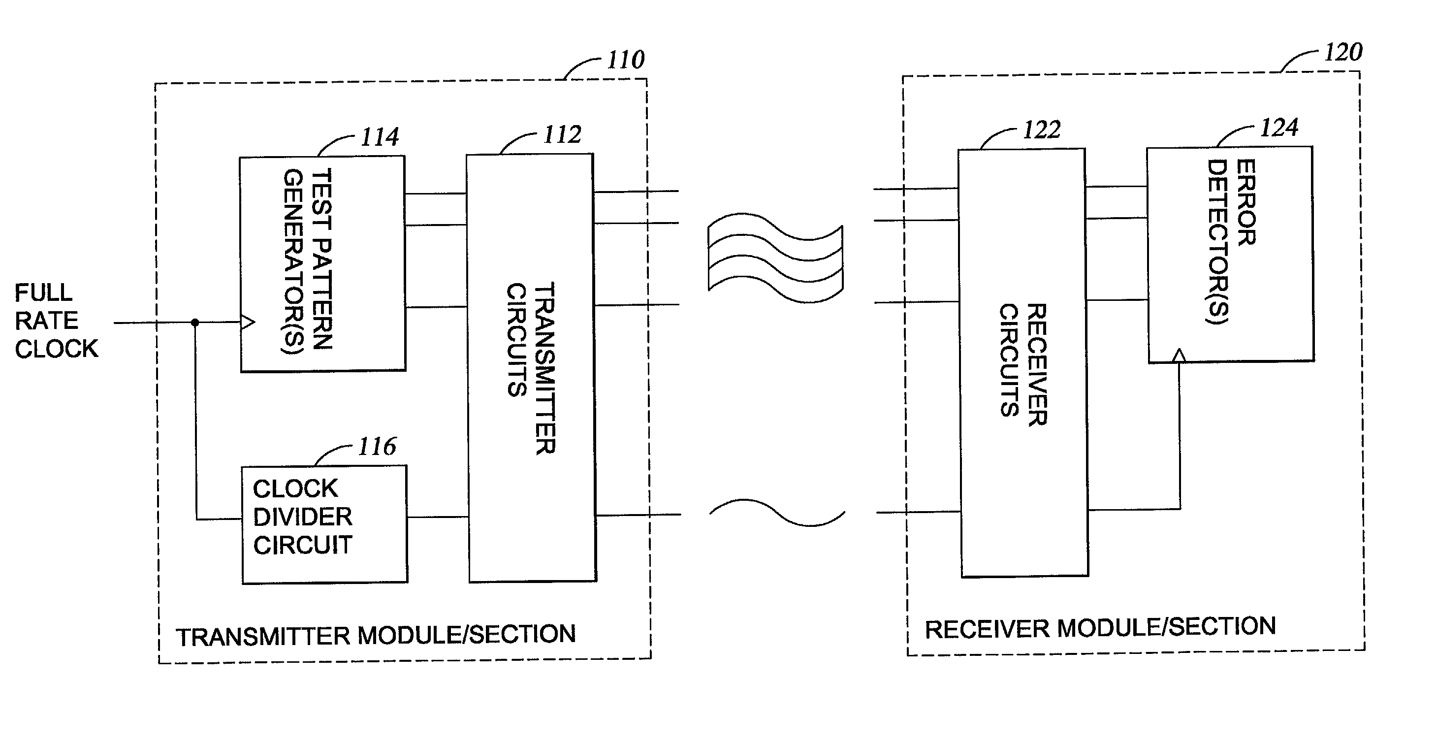
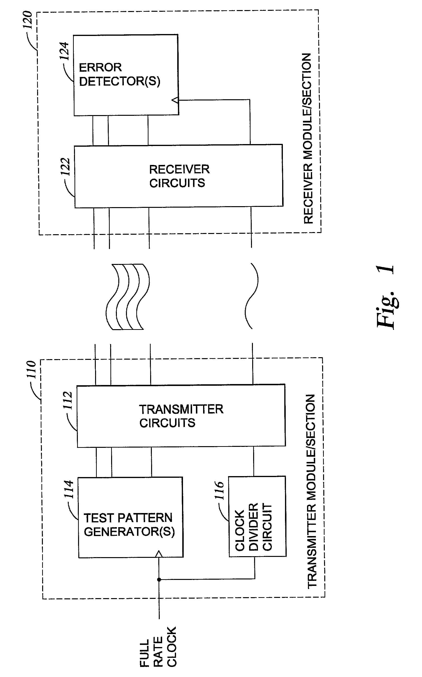
[0018] FIG. 1 is a schematic diagram illustrating an architecture for built-in self-testing of a parallel optical transceiver. As shown in FIG. 1, a parallel optical transceiver 100 generally comprises a transmitter module 110 and a receiver module 120. The parallel optical transceiver typically is housed in the same package, and each of the transmitter module and receiver module includes a plurality of input connections and output connections corresponding to the number of channels provided by the parallel optical transceiver. For example, a twelve channel parallel optical transceiver includes a twelve channel transmitter module having twelve sets of input / output connections and a twelve channel receiver module having twelve sets of input / output connections. As shown in FIG. 1, the output connections of the transmitter module are connected to the input connections of the receiver module. To test an individual parallel optical transceiver, the transceiver may be disposed on a test f...


PUM


Abstract

Method and apparatus for testing a parallel optical transceiver are provided. One embodiment provides a built-in self-testing (BIST) parallel optical transceiver comprising a full-rate clock test pattern generator and a clock divider circuit connected to provide a half-rate clock signal to one of the one or more transmitter channels, and an error detector comprising one or more error detection circuits connected to one or more receiver channels and configured to receive the half-rate clock signal. Another embodiment provides a method for testing a parallel optical transceiver, comprising: generating a full-rate clock test pattern to one or more transmitter channels; providing a half-rate clock signal to one of the one or more transmitter channels utilizing a clock divider circuit; transmitting test pattern and half-rate clock signals to one or more corresponding receiver channels; and detecting error utilizing one or more error detection circuits connected to receive the half-rate clock signal.

Description

BACKGROUND OF THE INVENTION[0001] 1. Field of the Invention[0002] The present invention generally relates to testing of optical transceivers. More particularly, the invention relates to built-in self-test of parallel optical transceivers.[0003] 2. Background of the Related Art[0004] The growth of electronic commerce, particularly via the internet, has produced exponential increases in the demand for communication bandwidth for computer networks as well as data storage and retrieval networks. In response to the communication bandwidth needs, optical fiber-based data communication devices are being developed. Most previously known optical link development has focused on serial transceivers (or transmitters and receivers). Recently, the focus has shifted to development of parallel transceivers because of the potential for high aggregate bandwidth and lower costs. Furthermore, parallel transceivers may be designed to handle data which has not been coded or serialized for transmission, w...

Claims


Application Information

Patent Timeline
Patent Type & Authority Applications(United States)
IPC IPC(8): G01R31/3187
CPCG01R31/3187
Inventor EWEN, JOHN F.SILJENBERG, DAVID W.WILKINSON-GRUBER, STEPHEN C.
Owner IBM CORP
Why Eureka
Try Eureka