

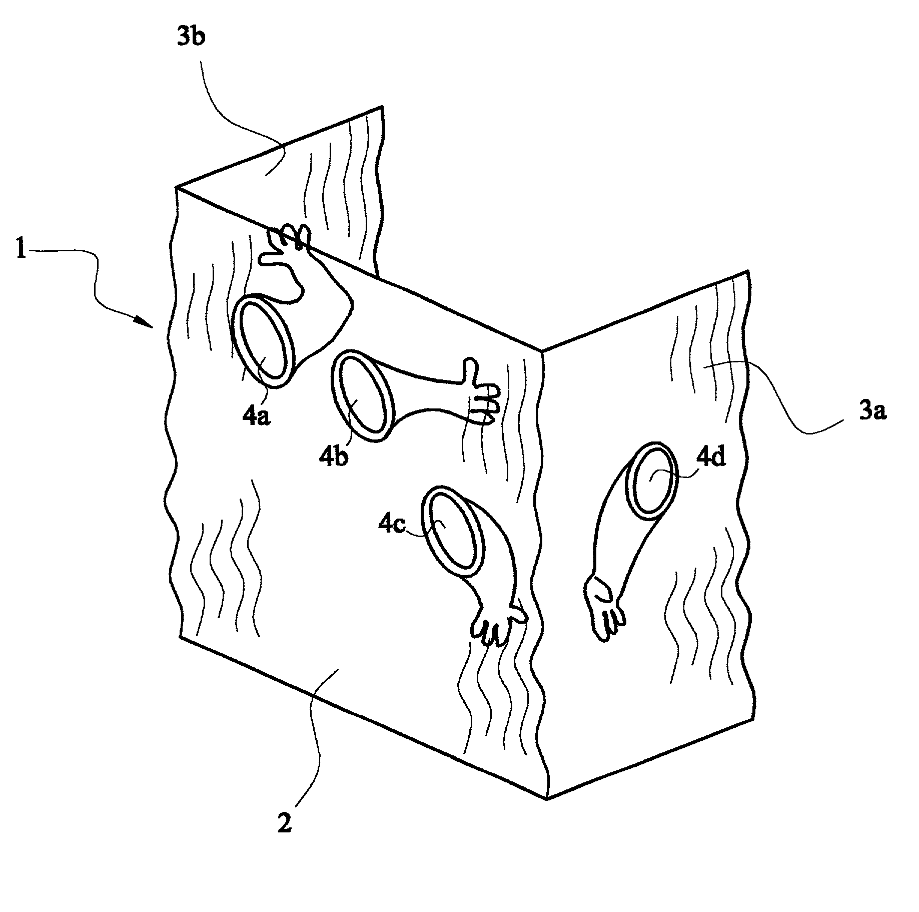
Containment assembly
a technology of containment and assembly, which is applied in the direction of building components, dirt cleaning, application, etc., can solve the problems of prohibiting unusually short or tall operators, affecting the operation of the operator, so as to improve the exposure level of operators, without hindering the access to (or maneuverability in)
- Summary
- Abstract
- Description
- Claims
- Application Information
AI Technical Summary
Benefits of technology
Problems solved by technology
Method used
Image

Examples
example
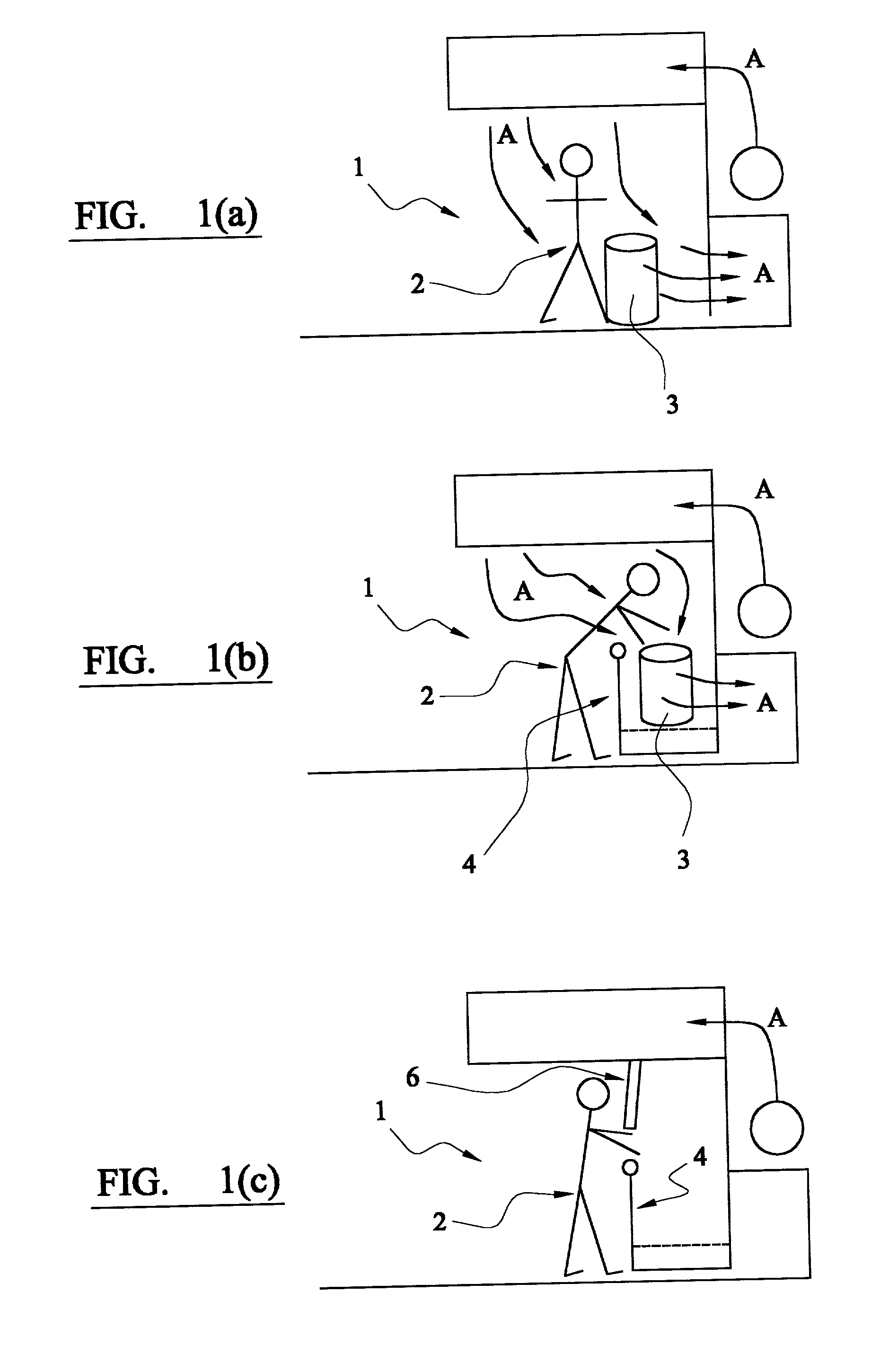
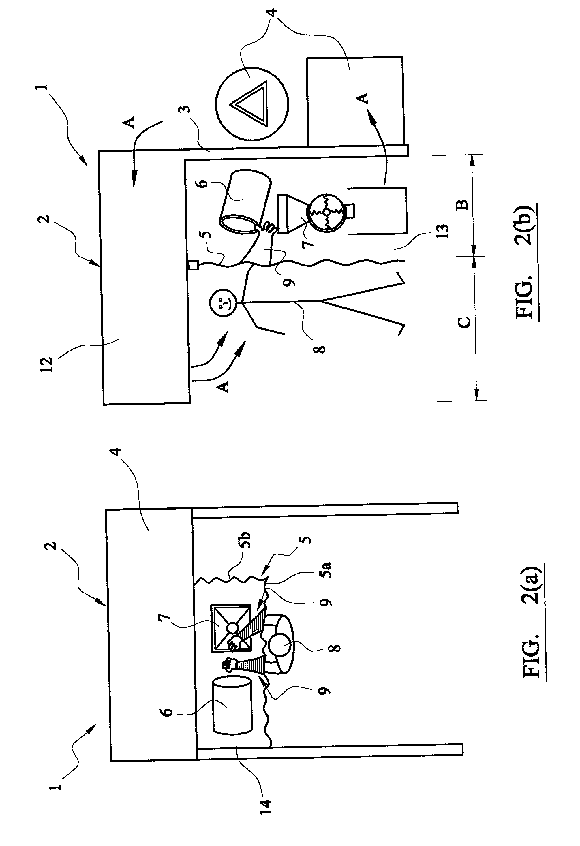
Factory Acceptance Testing of a Vacuum Transfer Down flow Booth
[0048] Two occupational hygiene (OH) air sampling surveys of the breathing zone and area air were conducted during factory acceptance testing (FAT) of a down flow booth (DFB) at Extract Technology Limited in Huddersfield, UK. The DFB is intended to be used for vacuum transfer of API from kegs. The primary objective of the surveys was to assess the effectiveness of the DFB compared with the design criteria of 10 .mu.g / m.sup.3 as measured in the operator's breathing zone during routine operations.
[0049] Protocol
[0050] Samples were collected using 25 mm IOM sampling head and glass fiber filters and calibrated Gilian air sampling pumps. Lactose was used as the placebo for the survey. An American Industrial Hygiene Association (AIHA) accredited laboratory (National Loss Control Service Corporation (NATLSCO)) analyzed the samples using the lactose OH sampling and analytical method.
[0051] To prepare the area for air sampling, a...
PUM
 Abstract
Description
Claims
Application Information