Brake booster

Inactive Publication Date: 2002-09-19
BOSCH AUTOMOTIVE SYST CORP
View PDF1 Cites 16 Cited by
  • Summary
  • Abstract
  • Description
  • Claims
  • Application Information

AI Technical Summary

Benefits of technology

0004] In view of the foregoing, it is an object of the present invention to provide a brake booster which is simple in c

Problems solved by technology

However, drawbacks are pointed out with conventional brake boosters as mentioned above.
On the other hand, in Application No. 35,474/1998, there is a need to provide a solenoid operated valve and a se

Method used


Image

  • Brake booster
  • Brake booster
  • Brake booster

Examples


Example

[0085] Second Embodiment

[0086] FIG. 10 shows a second embodiment of the present invention having length adjusting means 138 which is distinct form that used in the first embodiment. It should be understood that corresponding parts to those shown in the first embodiment are designated by like reference numerals as used before, to which 100 is added.

[0087] Specifically, the length adjusting means 138 comprises a cylindrical engaging member 135 slidably fitted around a stepped rod 134', which forms a front portion of a body 134 of a valve plunger 114, a detent member 136 which is loosely fitted in a through-opening 135a formed at a given circumferential position of the engaging member 135 so as to be radially movable therein, a cylindrical sleeve 137 surrounding the engaging member 135 and the detent member 136 and axially movable relative to the engaging member 135, and a spring 144 disposed between the sleeve 137 and the rear step 103e of a valve body 103 to urge the sleeve 137 forwa...


PUM


Abstract

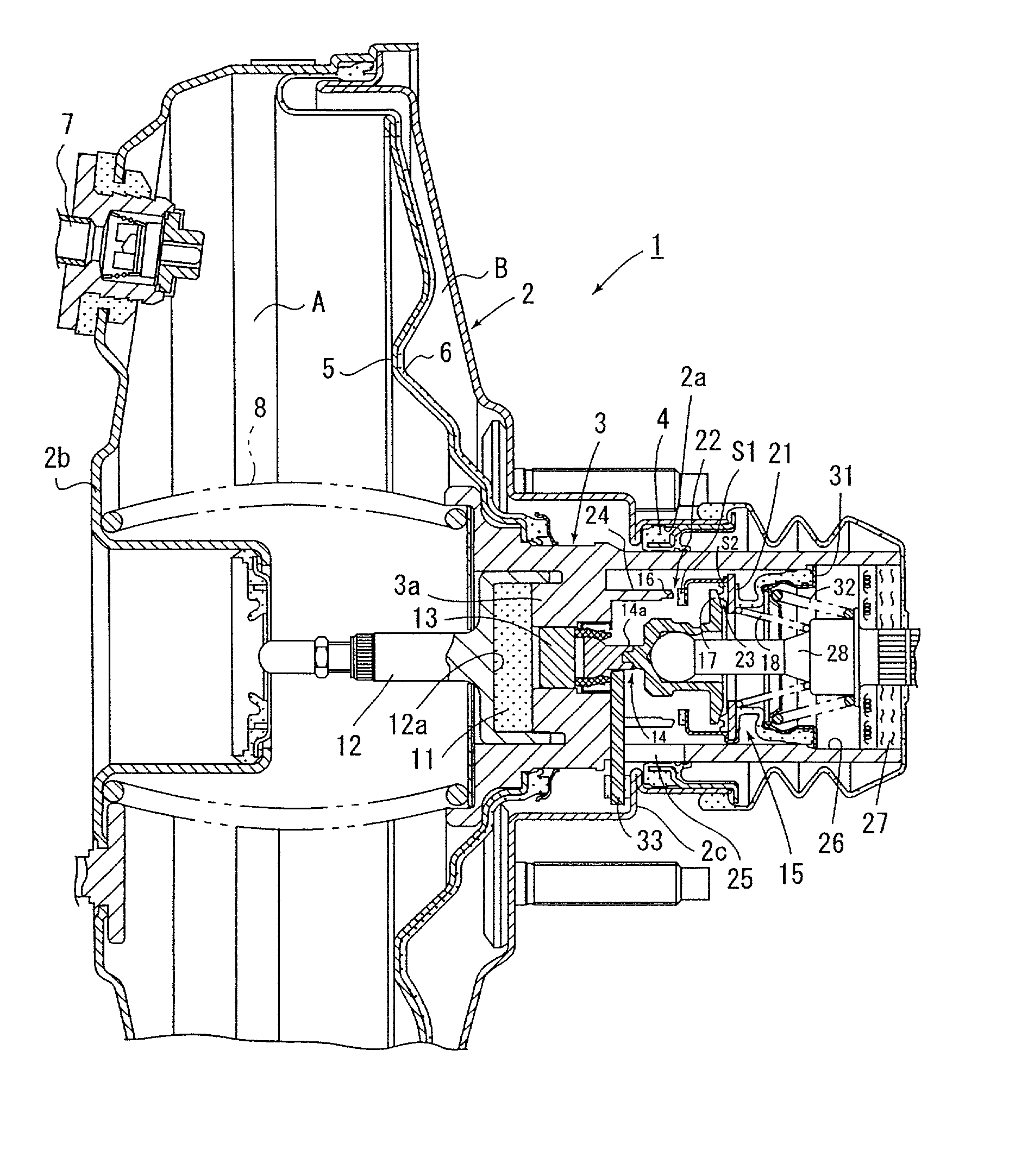
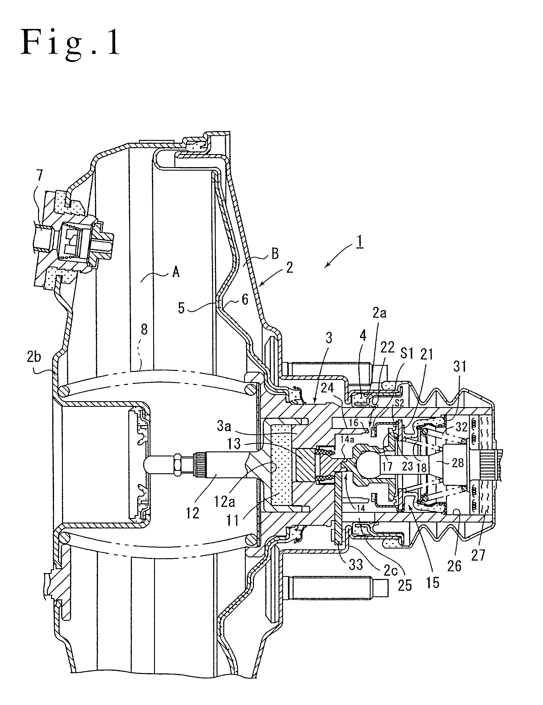
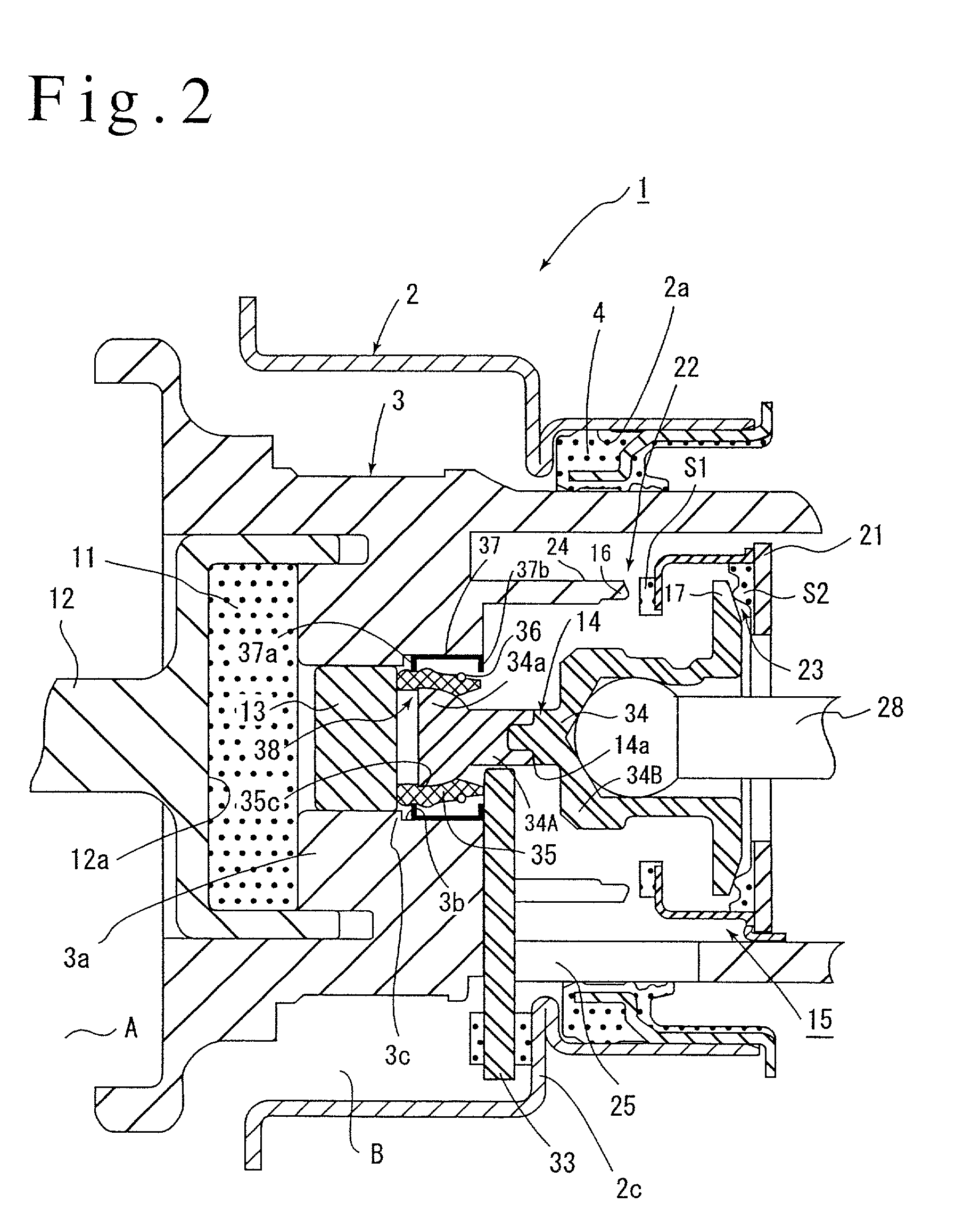
An improvement of a valve plunger 14 used in a brake booster 1. A valve plunger 14 comprises a rearwardly disposed body 34, and an engaging member 35 mounted on a front portion of the body 34. When a brake pedal is quickly depressed during an emergency brake operation, the engaging member 35 retracts rearward relative to the body 34, whereby the axial size of the entire valve plunger 14 is reduced, thereby increasing the opening of an atmosphere valve during the emergency brake operation as compared with a normal brake operation, allowing an output of an increased magnitude to be rapidly obtained. Thus, the invention allows an output from the brake booster 1 to be rapidly increased in immediate response to a quick depression of a brake pedal.

Description

FIELD OF THE INVENTION[0001] The invention relates to a brake booster, and more particularly, to a brake booster which assures that an increased output can be obtained reliably in response to a force of depression of a small magnitude which is applied to a brake pedal in the event a braking effort of an increased magnitude is required as in an emergency brake.DESCRIPTION OF THE PRIOR ART[0002] A brake booster which is arranged to permit an increased output to be obtained even in response to a braking depressing force of a small magnitude as in an emergency brake which requires a braking effort of an increased magnitude is known in the art, as exemplified by Japanese Patent No. 3,070,672 disclosing a brake booster in which in response to an input which exceeds a given value, an output gradient is increased subsequently to increase the output, or a Japanese Laid-Open Patent Application No. 35,474 / 1998 disclosing a brake booster in which an operation of a brake pedal is electrically de...

Claims


Application Information

Patent Timeline
IPC IPC(8): B60T13/52B60T7/12B60T8/32B60T13/57B60T13/575
CPCB60T7/12B60T8/3275B60T13/57B60T13/575B60T13/52
Inventor MACHIDA, MASAKAZUMORI, YASUSHI
Owner BOSCH AUTOMOTIVE SYST CORP
Why Eureka
Try Eureka