

Harness slack absorbing apparatus
- Summary
- Abstract
- Description
- Claims
- Application Information
AI Technical Summary
Benefits of technology
Problems solved by technology
Method used
Image

Examples
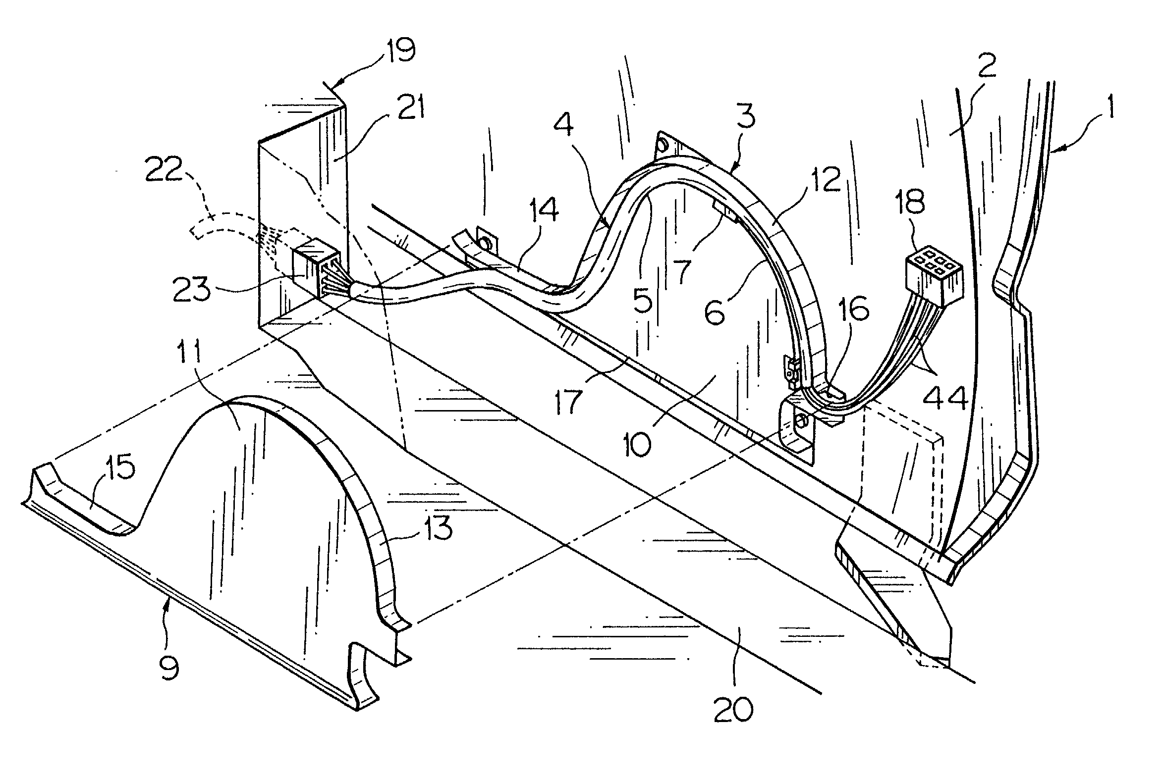
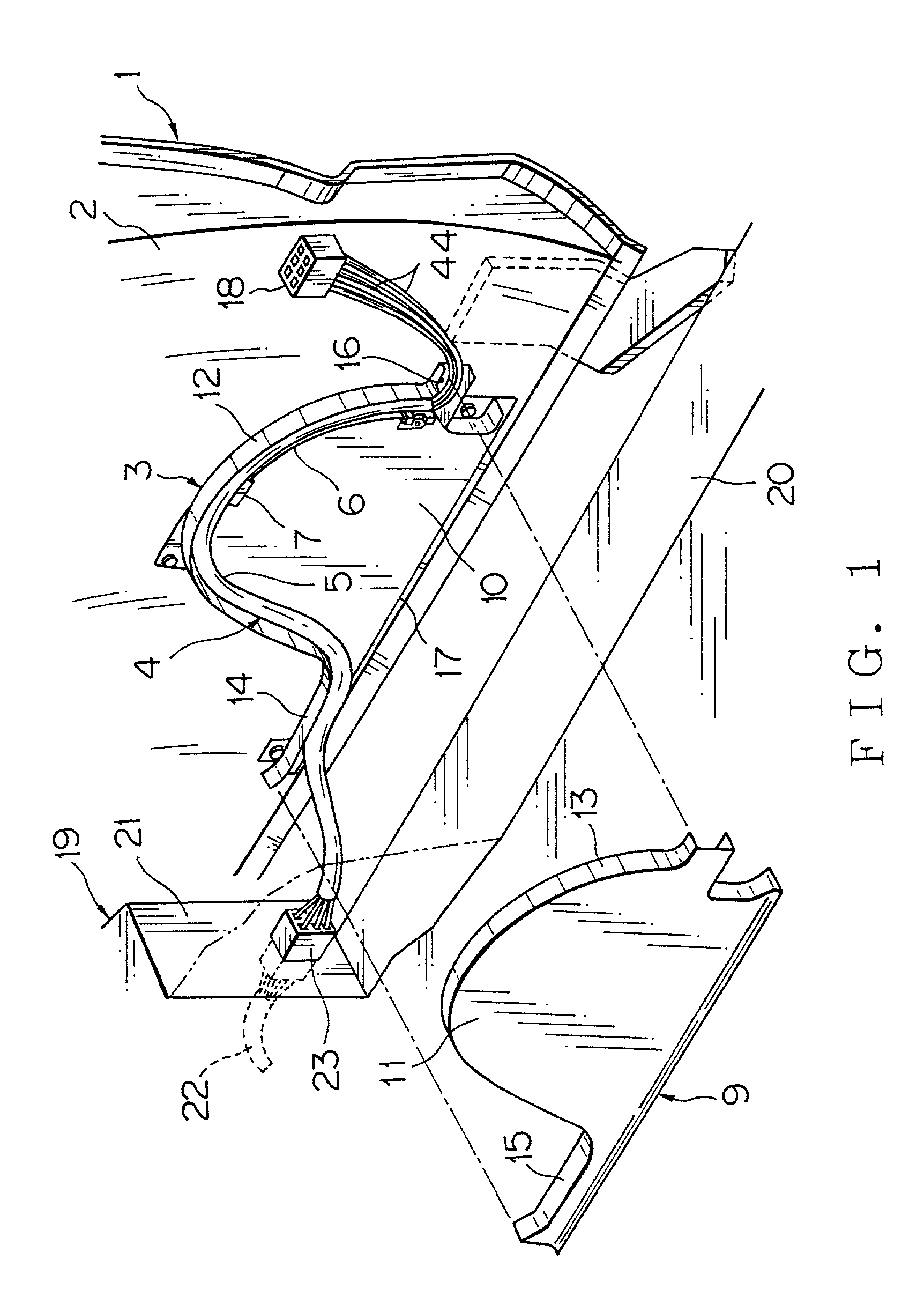
first embodiment
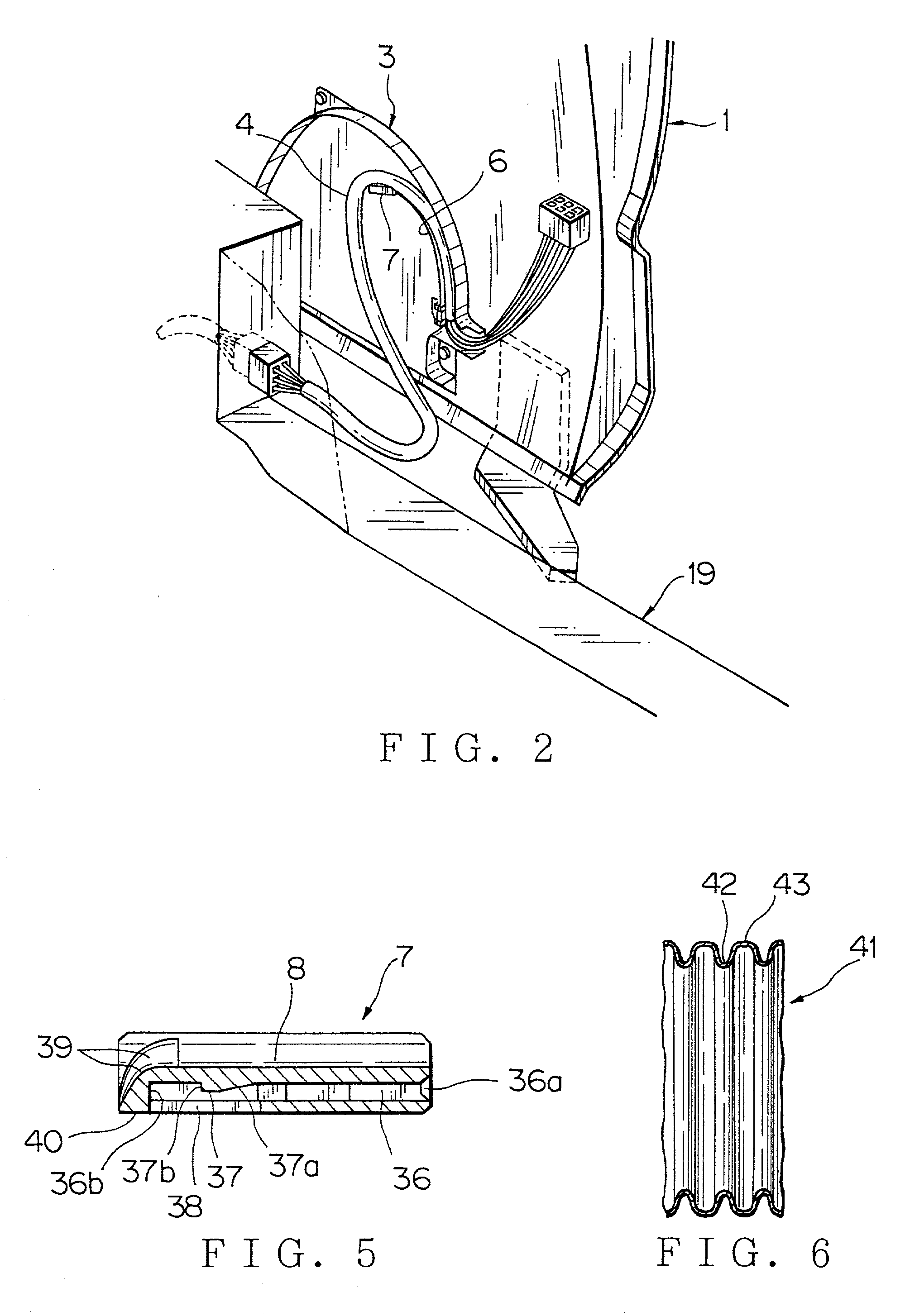
[0049] FIGS. 3 and 4 show the above described harness slack absorbing apparatus. As apparent from FIG. 3, a base end portion of the leaf spring 6 in this harness slack absorbing apparatus 81 is fixed to an insertion part 24 which is projected integrally from the base plate 10 of the protector body 3. To the distal end portion of the leaf spring 6, is fixed the above mentioned harness support member 7 provided with the recess 8 in a longitudinal direction. The leaf spring 6 may be made of metallic material, glass fiber or the like.
[0050] The insertion part 24 has a pair of vertical walls 25 and an insertion groove 26 in a form of a slit formed between the walls 25. The walls 25 respectively have cut-outs 27 in a rectangular shape at an intermediate position in a vertical direction. On the base plate 10 made of synthetic resin, there are integrally formed projections 28 for engagement with a fixing member 29, at both sides of the insertion part 24.
[0051] The leaf spring 6 also has a c...
second embodiment
[0065] FIGS. 7 and 8 show the harness slack absorbing apparatus according to the present invention.
[0066] Characteristic feature of this harness slack absorbing apparatus 82 is that the groove or recess 47 of the harness support member 46 to be fixed to the distal end portion of the leaf spring 6 is formed deep so that the wire harness 4 can be completely held in a lateral direction.
[0067] A depth of the recess 47 is substantially equal to a larger outer diameter of the corrugated tube (denoted also by reference numeral 4) having an oval shape in cross section. In case of employing the corrugated tube having a round shape in cross section, the depth of the recess 47 is substantially equal to the outer diameter of the corrugated tube. An inner width of the recess 47 is formed slightly larger than a width of the corrugated tube, so that the corrugated tube can smoothly slide inside the recess 47. The recess 47 is defined by vertical side walls 48 and a horizontal base wall 49. A heigh...
third embodiment
[0072] FIG. 9 shows the harness slack absorbing apparatus.
[0073] Characteristic feature of this harness slack absorbing apparatus 83 is that a harness support member 52 to be fixed to the distal end portion of the leaf spring 6 is formed in a substantially frame-like shape which can be divided vertically, and the wire harness 4 can be completely held along an entire circumference thereof.
[0074] The harness support member 52 is composed of a support member body 53 in a lower part made of synthetic resin to be fixed to the leaf spring 6, and a lid 54 made of synthetic resin to be locked with the support member body 53 by means of locking means. The support member body 53 and the lid 54 are respectively provided with recesses 55, 56 having a semi-elliptical shape in cross section, so that the corrugated tube (denoted also by reference numeral 4) having an elliptical shape in cross section can be held in the recesses 55, 56 so as to freely move in a longitudinal direction. Inner diamete...
PUM
 Abstract
Description
Claims
Application Information