Vehicle security system and method

Inactive Publication Date: 2002-09-26
INT COMP LTD
View PDF3 Cites 80 Cited by
  • Summary
  • Abstract
  • Description
  • Claims
  • Application Information

AI Technical Summary

Problems solved by technology

With these conventional systems, a driver can only use the vehicle for which he or she holds the

Method used


Image

  • Vehicle security system and method
  • Vehicle security system and method
  • Vehicle security system and method

Examples


Embodiment Construction

[0010] One vehicle security system and method embodying the invention will now be described by way of example with reference to the accompanying drawings.

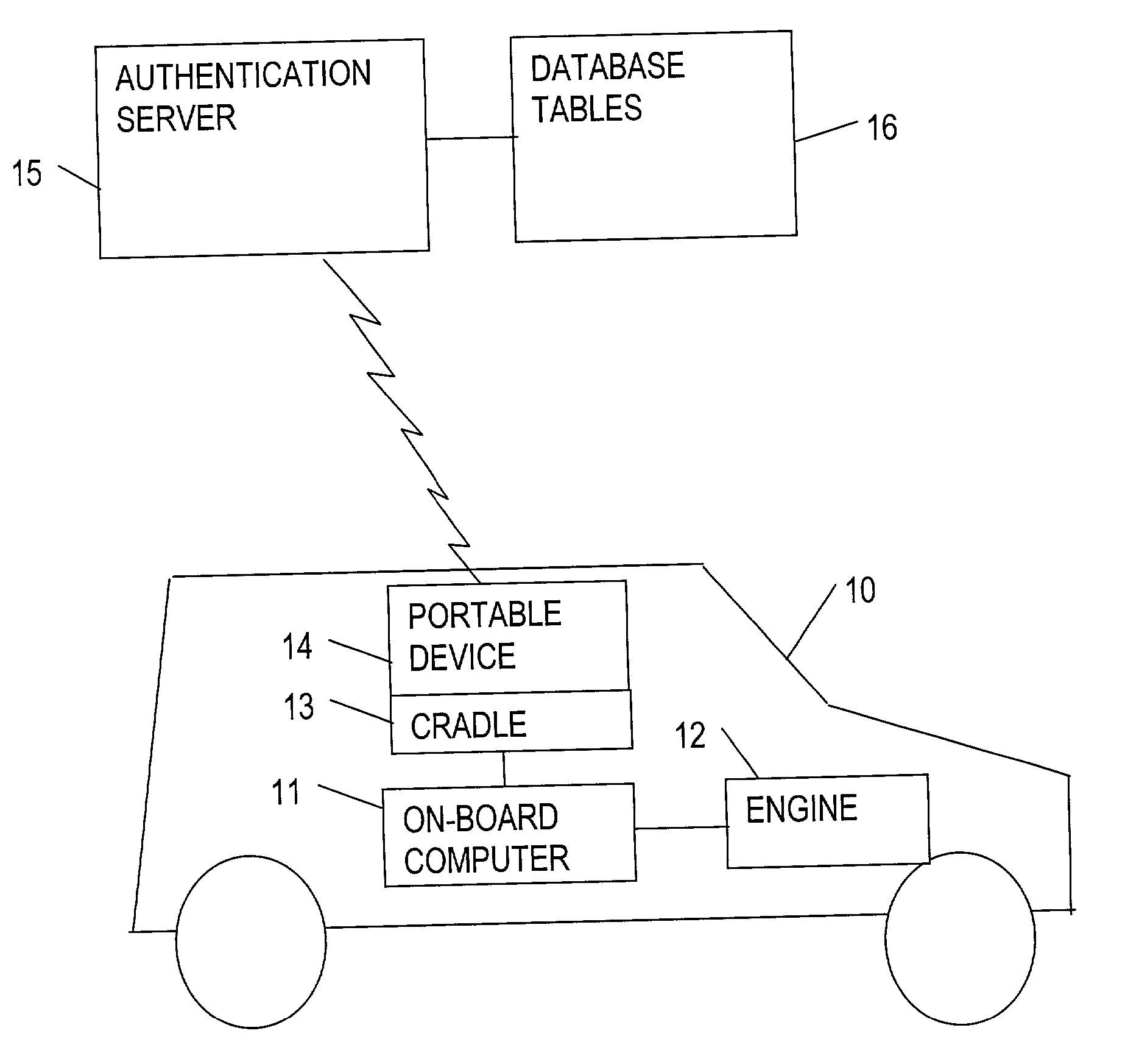
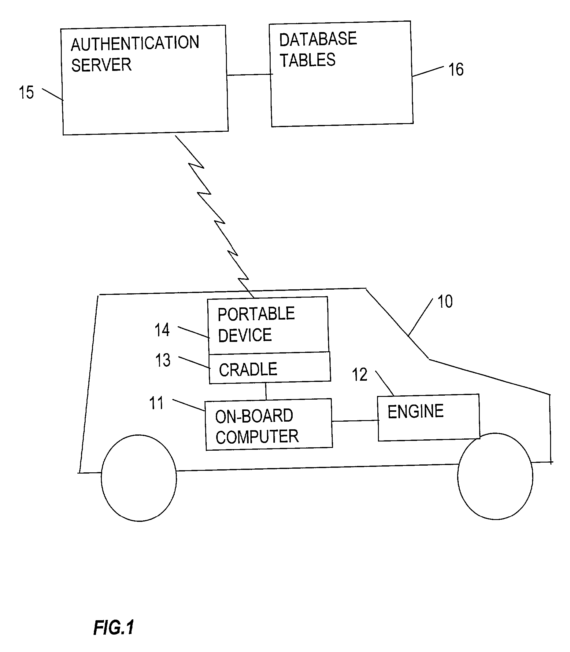
[0011] FIG. 1 shows a vehicle 10, having an on-board computer 11 which controls a number of systems in the vehicle, including the vehicle engine 12. The vehicle also includes a cradle 13, mounted for example on the vehicle dashboard. The cradle is adapted to receive a portable device 14, such as a pocket PC (personal computer) or PDA (personal digital assistant). When the portable device 14 is inserted into the cradle, it is connected to the on-board computer 11 by way of a data link. The cradle also supplies electrical power to the portable device.

[0012] When not in use in connection with the vehicle, the portable device 14 can be removed from its cradle and carried around by the user, for use in the normal manner as a pocket PC or PDA.

[0013] The portable device 14 includes a GPS (Global Positioning System) receiver, which supplie...


PUM


Abstract

A vehicle security system uses a portable device such as a pocket PC or PDA. When the device is inserted in a cradle in the vehicle, it communicates with the on-board computer to obtain the vehicle identity. The device then sends a request message, containing the vehicle identity and device identity, to a remote authentication server. The authentication server performs a number of checks, including checking that the device is authorized for use with this vehicle, and returns a response to the device. If the authentication is successful, the device allows the vehicle to be started. If the response from the authentication server is delayed, the vehicle may be started, but if the authentication check then fails, an on-line check will be compulsory the next time an attempt is made to start the vehicle.

Description

BACKGROUND TO THE INVENTION[0001] This invention relates to a system and method for improving vehicle security.[0002] Conventionally, vehicle security systems have relied on keys to lock / unlock doors and to control the vehicle ignition system. Remote control units (either infrared or radio frequency) have also been used, to control door locks or to enable / disable an engine immobilizer.[0003] With these conventional systems, a driver can only use the vehicle for which he or she holds the appropriate key or remote control unit. However, especially in the context of a fleet management system, it may be desired from time to time to vary the permissions for drivers to use vehicles. For example, it may be required to permit a driver to use a different vehicle (either temporarily or permanently), or to prevent a driver from using a particular vehicle, or to allow a driver to use more than one vehicle. This cannot be achieved easily with conventional systems.[0004] The object of the inventi...

Claims


Application Information

Patent Timeline
IPC IPC(8): B60R25/24G07C5/00G07C9/00
CPCB60R25/24B60R2325/205G07C5/008G07C9/00309G07C2009/00793
Inventor BUNYAN, ROY JAMES
Owner INT COMP LTD
Why Eureka
Try Eureka