
Data reproduction apparatus and data reproduction method

a data reproduction and data technology, applied in the field of data reproduction apparatus and data reproduction method, can solve the problems of image disordering continuing for a long time, bit error in received data, and inability to decode video frames

Inactive Publication Date: 2002-10-03
PANASONIC CORP
View PDF9 Cites 64 Cited by
  • Summary
  • Abstract
  • Description
  • Claims
  • Application Information

AI Technical Summary

Benefits of technology

[0033] The present invention is made to solve the above-described problems and has for its object to provide a data reproduction apparatus and a data reproduction method which can provide a display image on which the viewer hardly feels incongruity even when a transmission error occurs, and a data recording medium which contains a program for performing the data reproduction method by software.

Problems solved by technology

However, lengthening the repetition cycle of I-VOP, i.e., reducing the frequency of occurrence of I-VOP, is not desirable from the viewpoint of anti-error property, and it may cause that image disordering continues for a long time when a packet loss occurs.
Especially in a transmission system which includes a radio transmission line in a transmission path from a server to a receiving terminal, when the radio wave intensity at the receiving terminal is weak, transmitted data received by the terminal cannot be normally demodulated, resulting in a bit error in the received data.
Further, at the receiving terminal, unless data (video stream) equivalent to one frame (VOP) is prepared (stored), decoding of the video frame cannot be carried out.
However, since data of a target frame (target of decoding) is decoded with reference to a frame different from the frame that was referred to in the coding process, the display contents might be greatly disordered.
However, the conventional receiving terminal has previously been set so as to execute either of the above-mentioned two methods as a countermeasure against the occurrence of a transmission error and, therefore, the viewer sometimes feels considerable incongruity in the image displayed when a transmission error occurs.
However, from the viewpoint that the decoding process which has been in the abnormal state due to the occurrence of the transmission error should be quickly resumed to the normal decoding state, the frequency of occurrence of I frame (I-VOP) cannot be significantly reduced.

Method used


Image

  • Data reproduction apparatus and data reproduction method
  • Data reproduction apparatus and data reproduction method
  • Data reproduction apparatus and data reproduction method

Examples


embodiment 1

[0085] [Embodiment 1]

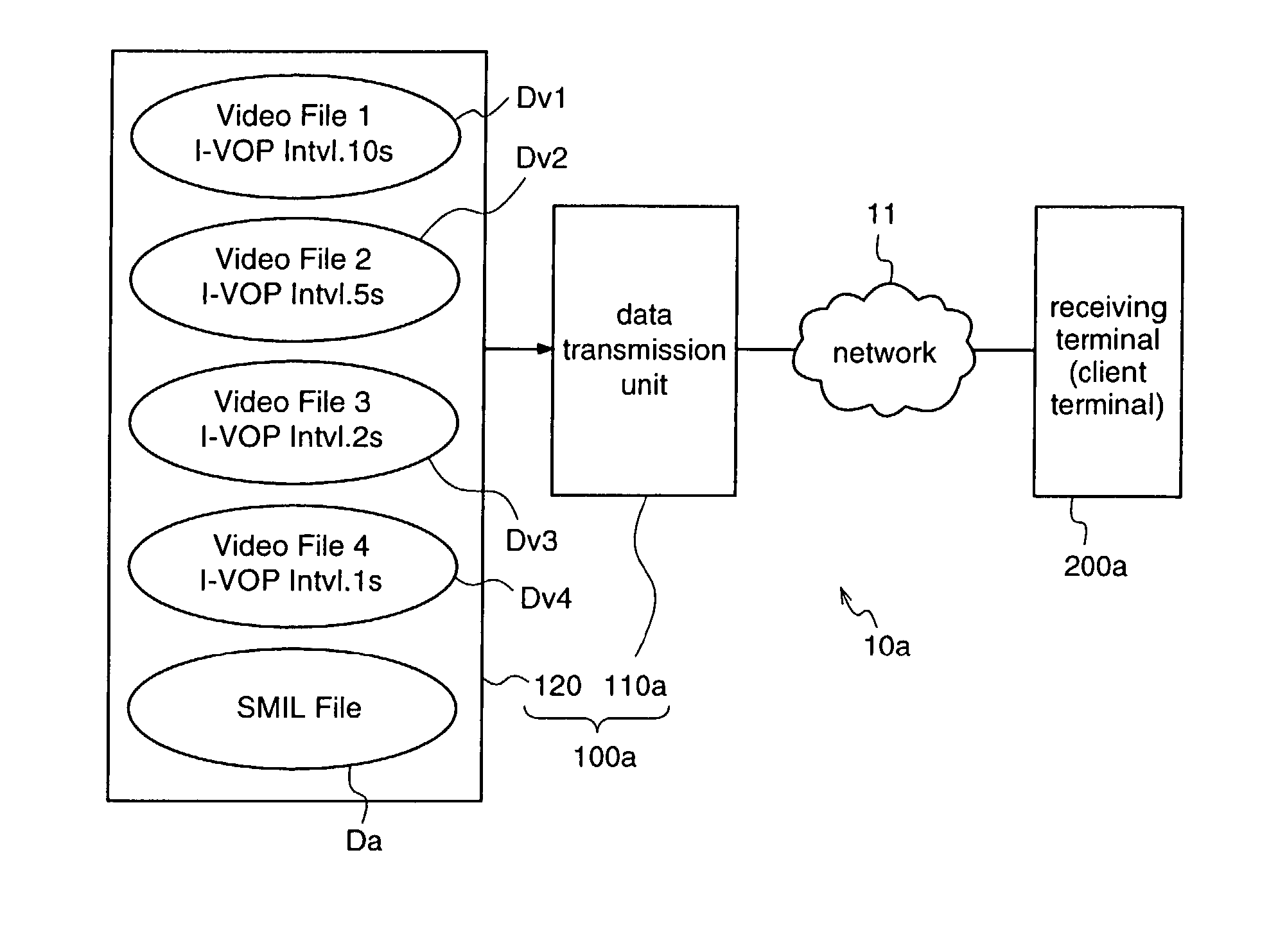
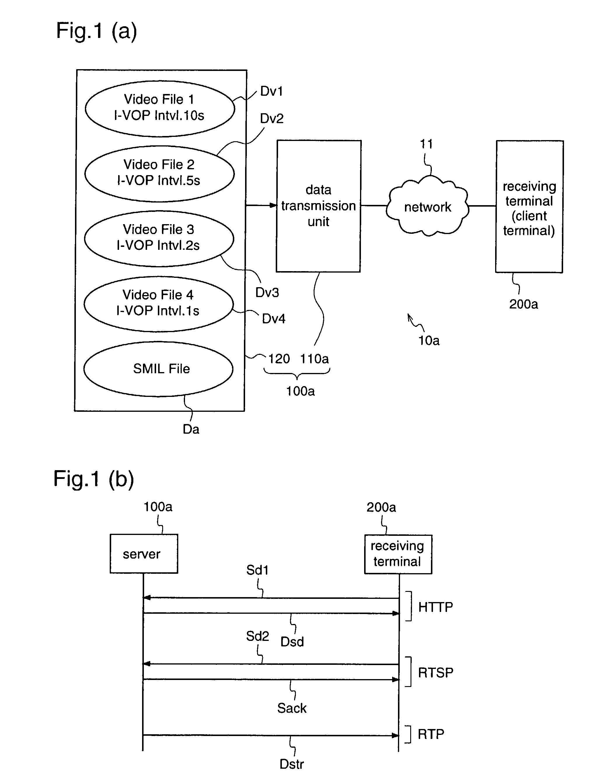
[0086] FIGS. 1(a) and 1(b) are diagrams for explaining a data transmission system 10a according to a first embodiment of the present invention, and FIG. 1(a) illustrates the construction of the system while FIG. 1(b) illustrates a data transmission process in the system.

[0087] The data transmission system 10a according to the first embodiment comprises a server 10a for outputting a predetermined video stream (coded video data); a receiving terminal (client terminal) 200a for receiving the video stream outputted from the server 10a, and reproducing video data; and a network 11 for transferring the video stream from the server 10a to the receiving terminal 200a.

[0088] The server 100a comprises a data storage unit 120 for holding plural video streams which are obtained by coding digital video signals corresponding to the same video sequence under different coding conditions, and holding SMIL data in which the attributes of the respective video streams are described...

embodiment 2

[0155] [Embodiment 2]

[0156] FIG. 7 is a block diagram for explaining a data transmission system 10b according to a second embodiment of the present invention, illustrating the constructions of a server and a client terminal in the system 10b.

[0157] The data transmission system 10b according to the second embodiment is provided with a client terminal (receiving terminal) 200b instead of the client terminal 200a of the data transmission system 10a according to the first embodiment. The client terminal 200b of this second embodiment determines a video stream having an optimum anti-error intensity on the basis of an anti-error intensity of video data to be received, which is set by the user, and the incidence of transmission error in RTP data Drtp from a server 10a, and then transmits a signal Sc designating the determined video stream to the server 10a.

[0158] To be specific, in the receiving terminal 200b, video data to be initially received is selected from among plural video data fil...

embodiment 3

[0250] [Embodiment 3]

[0251] FIG. 14 is a block diagram for explaining a data transmission system 10(c) according to a third embodiment of the present invention, illustrating the constructions of a server and a client terminal in the system 10(c).

[0252] In FIG. 14, the same reference numerals as those shown in FIG. 3 denote the same parts.

[0253] The data transmission system 10c is provided with a client terminal (receiving terminal) 200c and a server 100c instead of the client terminal 200a and the server 100a in the data transmission system 10a according to the first embodiment. The client terminal 200c provides the server 100c with information Drr relating to the transmission status, such as the incidence of transmission error in RTP data (RTP packets) supplied from the server, the packet arrival time, and the like, and the server 100c switches a video stream (RTP data) being transmitted from the server 100c to another video stream having a different coding condition, on the basis ...


PUM


Abstract

In a data transmission system, a server is provided with a data storage unit which holds plural video streams having different I-frame intervals, as coded data corresponding to the same video sequence, and a data transmission unit for transmitting a predetermined video stream among the plural video streams, according to a command signal Sc from a receiving terminal. The receiving terminal transmits a data designation signal (command signal) Sc which designates one of the plural video streams stored at the server end, to the server, on the basis of the contents of user setting. Therefore, at the receiving terminal, a video stream to be supplied from the transmitting end (server) can be selected between one having a high resistance to transmission error and one having a high video quality, according to the user's preference.

Description

[0001] The present invention relates to a data reproduction apparatus and a data reproduction method and, more particularly, to a data reproduction process in which anti-transmission-error property and video quality of video data to be obtained at a receiving end can be changed according to the user's preference or the occurrence status of transmission error, at the receiving end of the video data.[0002] In recent years, distribution of audio-visual data in narrow bands has become possible, as the international standard MPEG-4 (Moving Picture Experts Group Phase-4, ISO / IEC14496) relating to a compressive coding method for audio-visual data has been established. For example, a transmission path having a band width of 64 kbit / sec can transmit video data having 176 pixels in the horizontal direction and 144 pixels in the vertical direction within one frame and a frame rate of 5.about.6 frames / sec, and audio data having a quality as high as telephone quality, simultaneously.[0003] In a ...

Claims


Application Information

Patent Timeline
IPC IPC(8): G11B20/10H04N7/24
CPCH04N21/234327H04N21/23439H04N21/2381H04N21/25808H04N21/25858H04N21/2662H04N21/8543H04N21/440227H04N21/47202H04N21/485H04N21/6377H04N21/6437H04N21/658H04N21/41407G11B20/10
Inventor MATSUI, YOSHINORI
Owner PANASONIC CORP
Learn More