Magnetically levitated motor

a technology of magnets and motors, applied in the direction of mechanical energy handling, mechanical apparatus, windings, etc., can solve the problems of complex structure, difficult to increase the speed of the motor, and complex control of the levitation for

Inactive Publication Date: 2002-10-24
SANKYO SEIKI MFG CO LTD
View PDF6 Cites 11 Cited by
  • Summary
  • Abstract
  • Description
  • Claims
  • Application Information

AI Technical Summary

Benefits of technology

[0008] In accordance with one embodiment of the present invention, a magnetically levitated motor may comprise a stator having windings for rotation and windings for levitation, and a rotor having a rotor magnet magnetized in multiple poles, the stator and the rotor being disposed opposite to each other, wherein a rotary shaft of the rotor is levitated in a direction orthogonal to an axis of the rotor and rotationally driven by magnetic force, wherein the rotor magnet includes four magnetic poles provided adjacent to one another in a rotational direction at intervals of 90 degrees, and each of the windings for rotation and the windings for levitation has concentrated windings spaced at intervals of 30 degrees in a rotational direction to provide induction conductive winding sections at twelve locations. In one aspect of the present invention, each two of the induction conductive winding sections spaced at an interval of 90 degrees among the induction conductive winding sections at twelve locations are connected to form one winding set such that six winding sets are formed in total in each of the windings for rotation and the windings for levitation, and current for rotation and current for levitation are conducted through the respective six winding sets to perform rotation and levitation of the rotor. As a result, substantially perfect levitation and rotation can be achieved.
[0009] Moreover, separations between the induction conductive winding sections in the winding sets, which respectively correspond to going paths and returning paths in windings, are set at intervals of 90 degrees, which correspond to the separations of the rotor magnets. Therefore, its driving frequency is reduced by half, compared to, for example, a magnetically levitated motor with a rotor magnet having eight magnetic poles and a winding having six poles. As a result, in accordance with the present embodiment, a driving amplifier with a greater speed is not necessary, and heat generation and lowered efficiency that may be caused by an increase in iron loss can be effectively prevented.
[0010] In accordance with another embodiment of the present invention, stators and rotor may be formed in a planar confronting configuration, and two planar rotor magnets may be arranged in a direction of a rotor axis of the rotor. The stators may be disposed on both sides of the two planar rotor magnets to be interposed by the stators, and a winding for rotation and a winding for levitation may be mounted on each of the stators. As a result, greater levitation force and rotational torque are obtained, and controls of space four axes except the positional control in the rotational axis direction can be performed.
[0011] Furthermore, in accordance with still another embodiment of the present invention, a magnetically levitated motor may be formed in a cylindrical-confronting configuration, and a pair of stator-rotor sets in the cylindrical-confronting configuration may be arranged in a direction of the rotational axis. The motor having this configuration is also capable of producing greater levitation force and rotational torque, and performing controls of space four axes except the position control in the rotational axis direction.

Problems solved by technology

However, the conventional magnetically levitated motor described above requires a complex magnetic flux distribution for the stator, which results in a complex structure, and complex levitation force control is required.
Accordingly, it is difficult for the motor to increase the motor speed, and there is a problem in that the levitation force is weak and therefore its efficiency is unsatisfactory.

Method used


Image

  • Magnetically levitated motor
  • Magnetically levitated motor
  • Magnetically levitated motor

Examples


Embodiment Construction

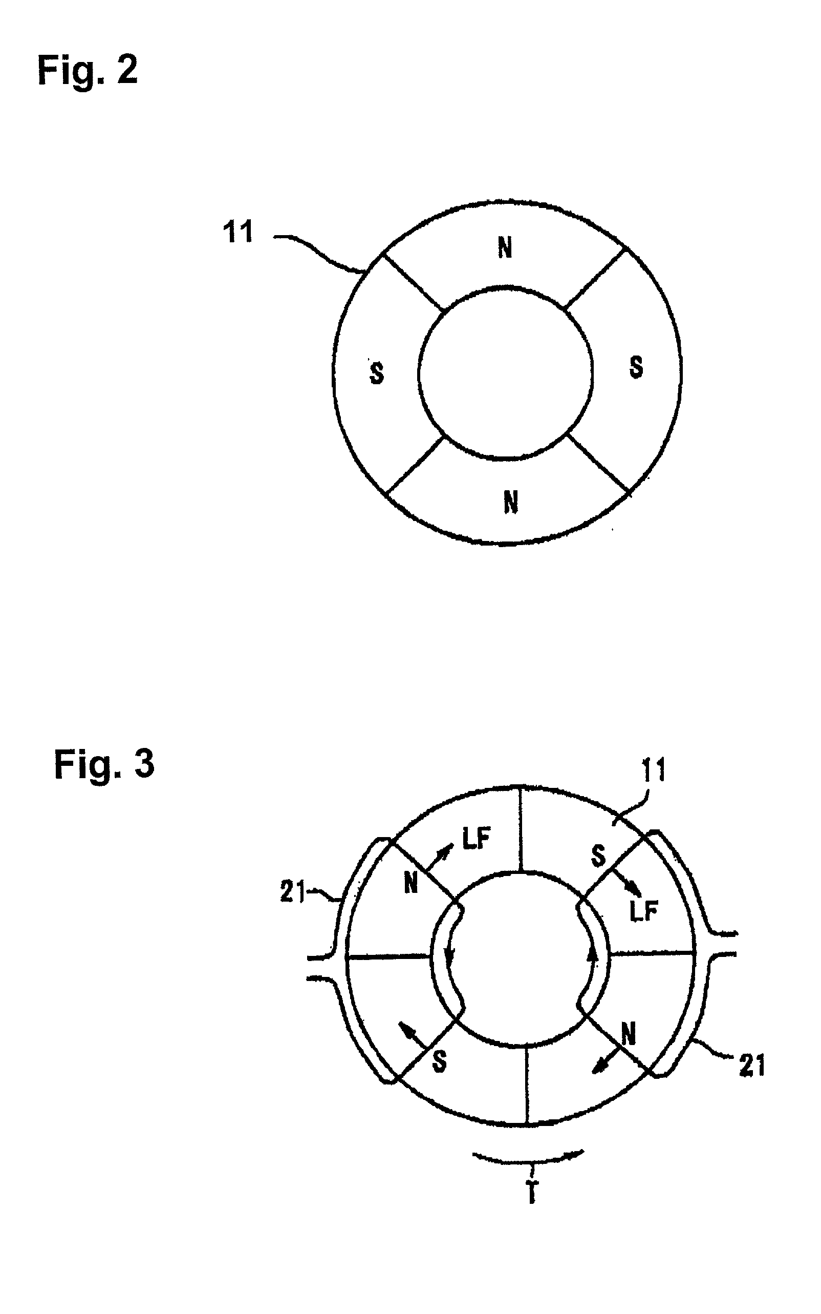
[0026] A magnetically levitated motor in accordance with one embodiment of the present invention is described below with reference to the accompanying drawings. First, principles for generating rotational torque and levitation force (bearing force) with windings and rotor magnets are described prior to a concrete description of the structure of the magnetically levitated motor.

[0027] First, to generate a rotational torque, currents that are in phase are conducted in diagonally located two windings in a winding group for rotation 21, as shown in FIG. 3. Lorentz forces LF that are opposite to each other are generated in the windings based on the currents. As a result, a rotational torque T is generated. In the mean time, to generate a levitation force (bearing force), currents having opposite phases are conducted in diagonally located windings in a winding group for bearing 22, as shown in FIG. 4, to thereby generate Lorentz forces LF in the same direction by the currents to generate ...


PUM


Abstract

A rotor includes four magnetic poles provided in a rotational direction at intervals of 90 degrees. A stator includes a winding group for rotation and a winding group for levitation. Each of the winding groups has concentrated windings spaced at intervals of 30 degrees in a rotational direction to provide induction conductive winding sections at twelve locations. Each two of the induction conductive winding sections spaced at an interval of 90 degrees among the twelve induction conductive winding sections are connected to form one winding set such that six winding sets are formed in total in each of the winding groups. Current for rotation and current for levitation are conducted through the six winding sets in the windings for rotation and levitation to perform rotation and levitation controls of the rotor.

Description

[0001] 1. Field of the Invention[0002] The present invention relates to a magnetically levitated motor that magnetically, rotationally supports a rotor in a non-contact manner.[0003] 2. Description of Related Art[0004] Conventionally, magnetic bearings that support a rotary body in a non-contact matter are used in various fields. In recent years in particular, radial magnetically levitated motors that integrate a function as a magnetic bearing and a function as a motor have been proposed. A magnetically levitated motor has an advantage in that torque generation for a rotor and positional control of a rotor shaft can be simultaneously performed.[0005] For example, a conventional magnetically levitated motor is equipped with a stator having magnetic poles formed on its inner circumferential surface in which each of the poles is wound with a single-pole winding, a rotor having M number of magnetic poles that are composed of permanent magnets and confronted with the inner circumferentia...

Claims


Application Information

Patent Timeline
Patent Type & Authority Applications(United States)
IPC IPC(8): F16C32/04F16C39/06H02K3/04H02K3/28H02K7/09H02K21/14H02K21/24H02K29/00
CPCF16C32/0468H02K7/09F16C32/0493F16C2380/26
Inventor KANEBAKO, HIDEKIOKADA, YOHJIABE, KEISUKE
Owner SANKYO SEIKI MFG CO LTD
Why Eureka
Try Eureka