Power plant

a power plant and power technology, applied in the field of power plants, can solve the problem that the desired energy efficiency cannot be achieved, and achieve the effect of efficient us

Inactive Publication Date: 2002-10-31
YASUDA TERUYOSHI +1
View PDF0 Cites 3 Cited by
  • Summary
  • Abstract
  • Description
  • Claims
  • Application Information

AI Technical Summary

Benefits of technology

0023] This feature of the present invention enables providing a power plant which can employ a sandwich structure composed of the groups of n permanent magnets consisting of N pole and S pole combinations and the n exciting coils, which utilizes the torque of rotor attributed to the dimensional difference, with respect to the axle, between the position of n electromagnets and the position of magneto coil of generator and which enables efficient takeout, from the turning force takeout part of the axle, of a rotational energy greater than an energy equivalent to an input power applied to the electromagnetic force imparting means. Further, an output power greater than the input power applied to the electromagnetic force imparting means can be efficiently taken out from the generator.

Problems solved by technology

Further, this power plant has a drawback in that it is not so constituted as to utilize the torque of a rotor with the result that any desirable energy efficiency cannot necessarily be attained.

Method used


Image

  • Power plant
  • Power plant
  • Power plant

Examples


Embodiment Construction

[0065] The present invention will now be described in greater detail with reference to the following Embodiments, which should not be construed as limiting the scope of the invention.

[0066] One embodiment of the present invention based on the above principle will be described with reference to FIGS. 1 and 2 and FIGS. 9 to 11.

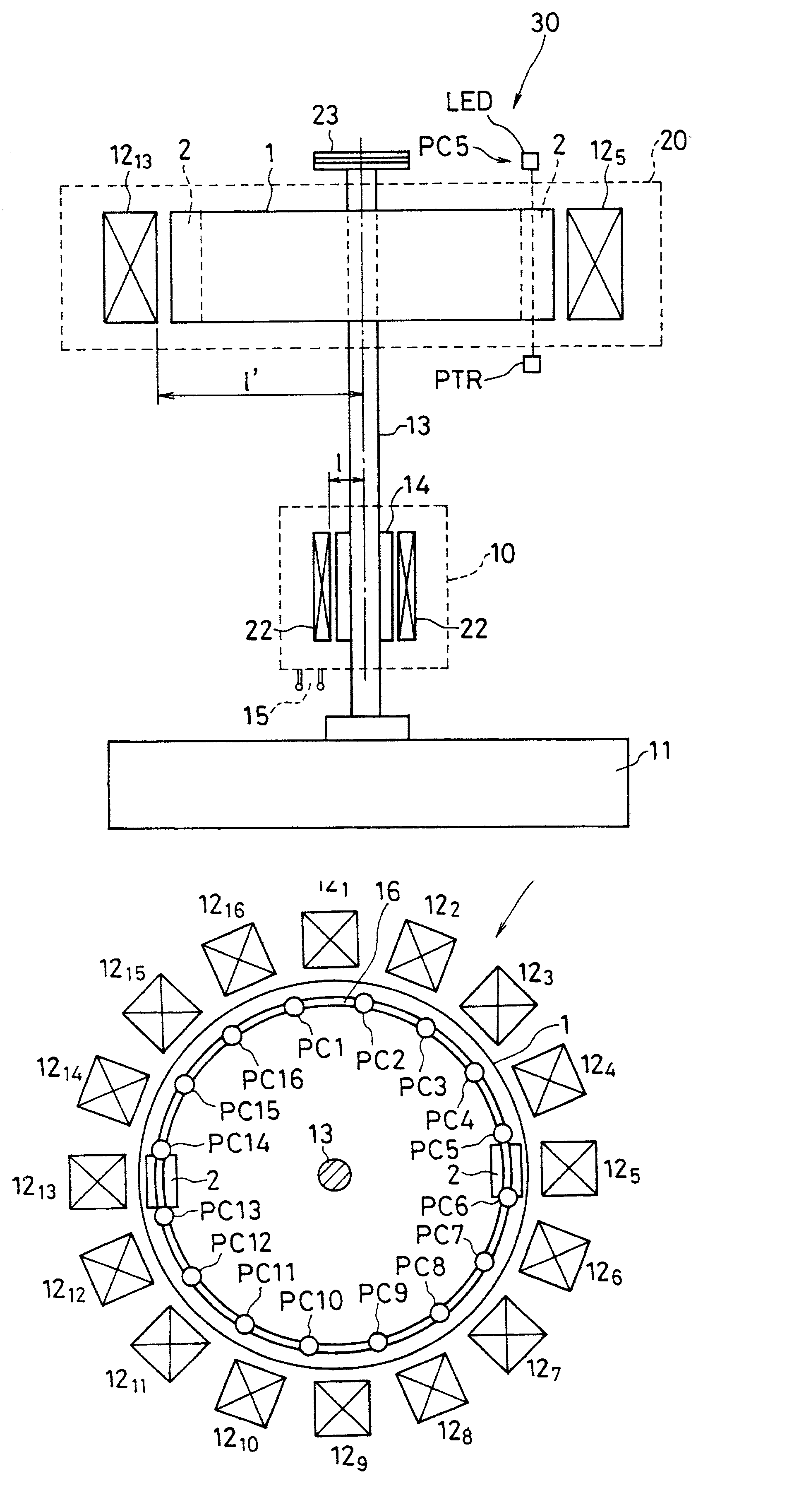
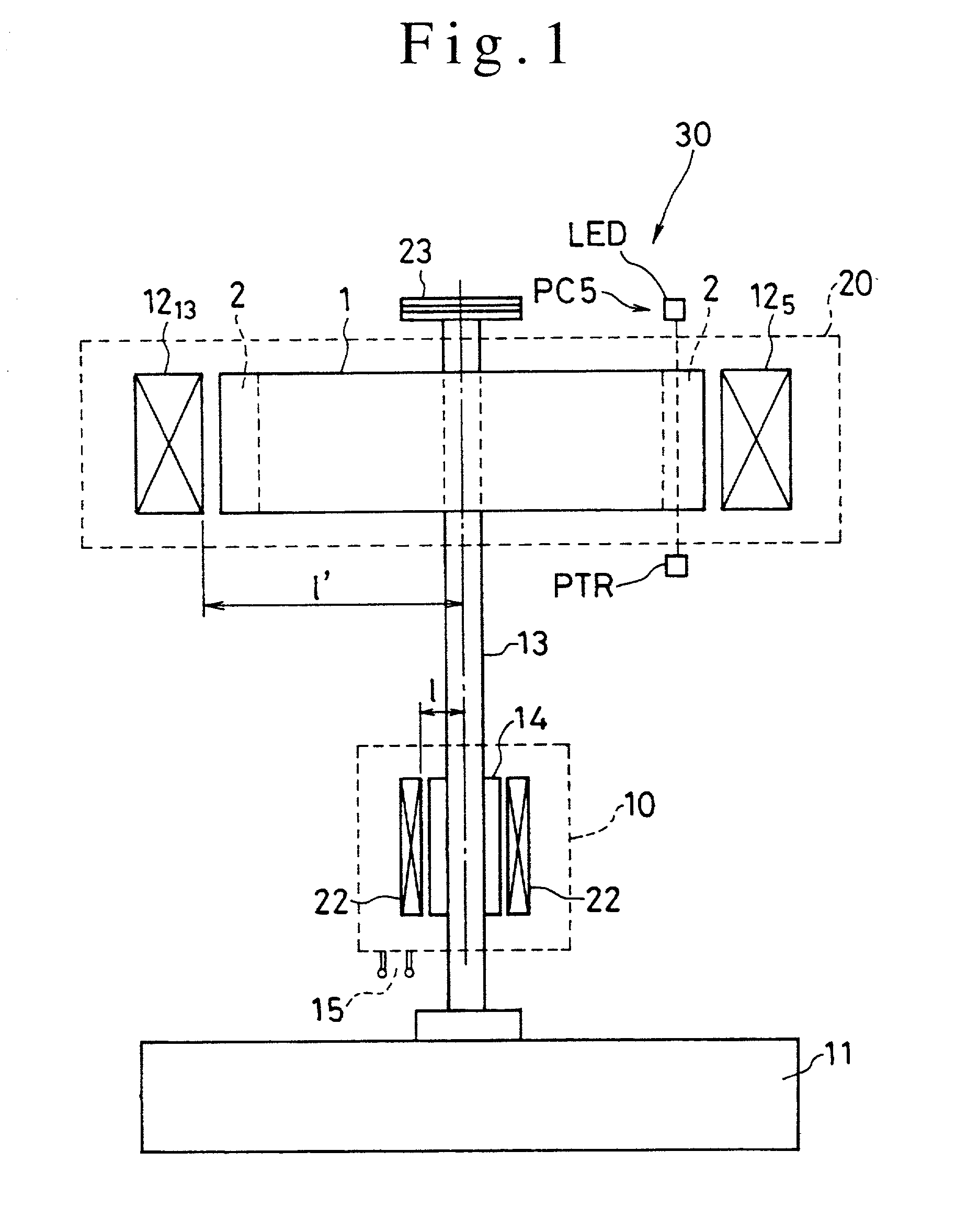
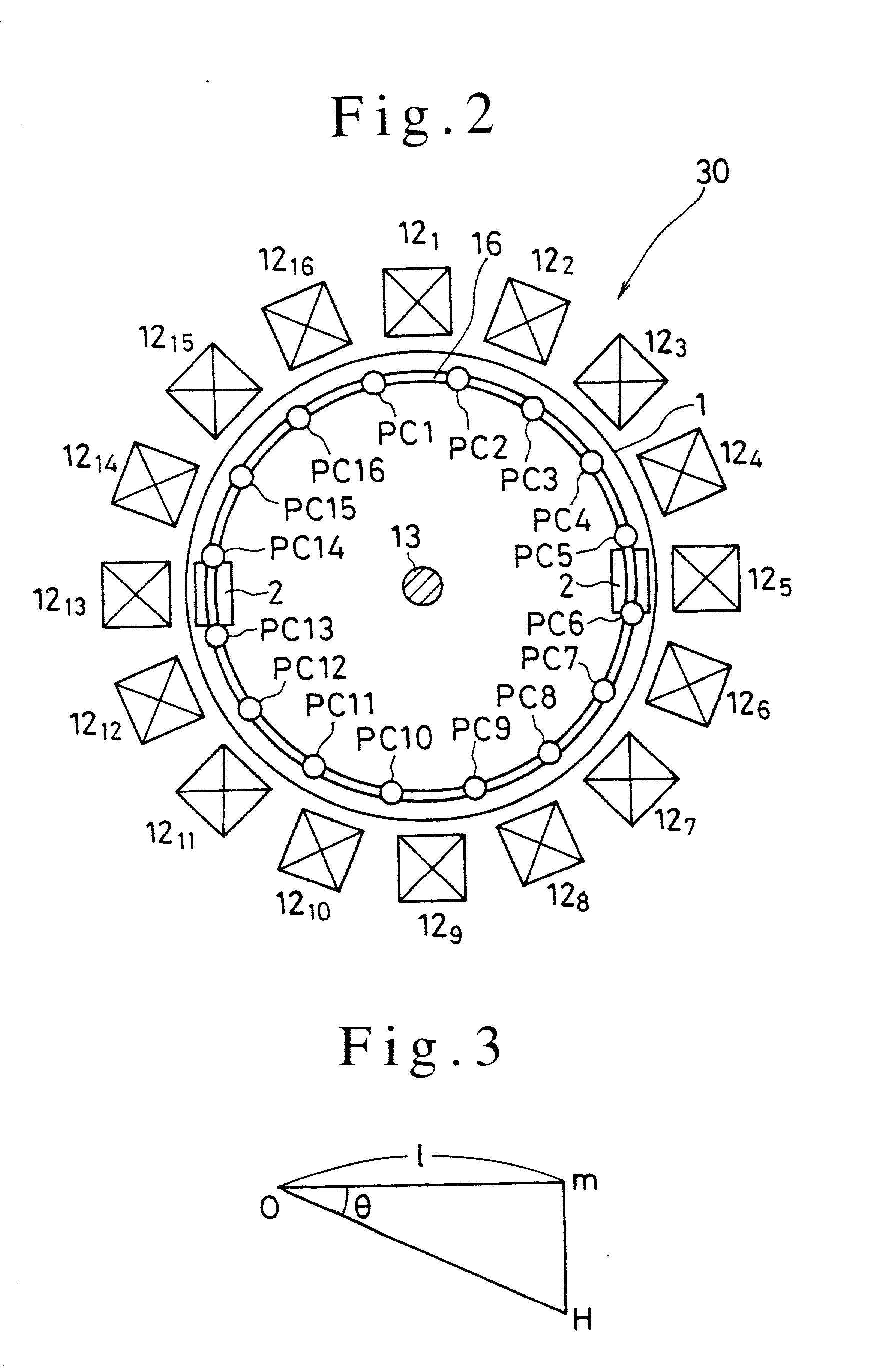
[0067] Power plant 30 according to one embodiment of the present invention, shown in FIGS. 1 and 2, has such a structure that base 11 rotatably supports axle 13 perpendicularly erected thereon and that a lower part of the axle 13 is fitted with generator 10 for taking out an output power while an upper part of the axle 13 is fitted with motor unit 20 to which an input power is fed, including disk-shaped rotor 1 fixed to the axle 13. An end portion of the axle 13 is fitted with a power takeout part, for example, pulley 23.

[0068] The generator 10 comprises rotator 14 fixed to the axle 13 and, arranged round the outer periphery of the rotator 14, magneto coil 22, s...


PUM


Abstract

A power plant comprising axle 13 fitted with a turning force takeout part and, coaxially arranged thereon, generator 10 capable of outputting a power and rotor 20 driven and rotated by an electromagnetic force imparting means, said electromagnetic force imparting means capable of producing an electromagnetic force with the use of an input power, wherein, with respect to the axle 13, a dimension of position of imparting of a rotary driving force to the rotor in the electromagnetic force imparting means is larger than a dimension of position of output power production in the generator 10 to thereby enable takeout, from the turning force takeout part of the axle 13, of a rotational energy greater than an energy equivalent to an input power applied to the electromagnetic force imparting means. Further, an output power greater than the input power can be taken out with the use of the power plant. The takeout of an output energy greater than the input power is advantageous from the viewpoint of meeting the demand for resource saving and energy saving.

Description

[0001] The present invention relates to a power plant wherein permanent magnets and electromagnets are combined with each other so as to obtain an increased rotational energy.[0002] Inventions wherein permanent magnets and electromagnets are combined with each other to thereby constitute a power plant in an attempt to obtain an output greater than an input power have been proposed (see, for example, Japanese Patent Application Laid-open Specification No. 7(1995)-87725).[0003] However, for example, the power plant disclosed in the above Japanese Patent Application Laid-open Specification No. 7(1995)-87725 has a complex constitution including not only permanent magnets and electromagnets but also, for example, a rotary balancer. Further, this power plant has a drawback in that it is not so constituted as to utilize the torque of a rotor with the result that any desirable energy efficiency cannot necessarily be attained.OBJECT OF THE INVENTION[0004] The present invention has been made ...

Claims


Application Information

Patent Timeline
Patent Type & Authority Applications(United States)
IPC IPC(8): F03G7/00H02K53/00
CPCH02K53/00
Inventor YASUDA, TERUYOSHIOTA, SADAMASA
Owner YASUDA TERUYOSHI
Why Eureka
Try Eureka