
Form identification method

a form identification and rectangle technology, applied in the field of form identification methods, can solve the problems of unstable operation of extracting each rectangle in the form, and no consideration is given with respect to the features of lines, character lines, cells which are peculiar to the form imag

Inactive Publication Date: 2002-10-31
HITACHI LTD +1
View PDF6 Cites 19 Cited by
  • Summary
  • Abstract
  • Description
  • Claims
  • Application Information

AI Technical Summary

Benefits of technology

[0021] A second object of the invention is to provide a form identification method whereby control information is provided every form which has previously been registered or every cell of the form, a type of cell line, for example, a solid line or a broken line is used, and an identifying mode is switched to either a mode to identify the forms in which the types of cell lines are different although shapes of the cells are the same as different types of forms or a mode to identify the forms in which the types of cell lines are different as same type of forms, thereby enabling the type of form to be identified.
[0022] A third object of the invention is to provide a form identification method which can identify a type of form at high precision even if there is a location shift of the form.
[0023] A fourth object of the invention is to provide a form identification method which can stably identify a type of form at high precision even if there is a dropout due to a blur or the like of lines or an appearance of a false line or even if there are enlargement and shrinkage (or scale-up and scale-down) of the form.

Problems solved by technology

Further, as a conventional technique regarding the form identification of a form such that the operation to extract each rectangle in the form is unstable because of the enlargement and shrinkage (or scale-up and scale-down) of the form, a blur of the lines, or the like, for example, the technique disclosed in JP-A-2000-306030 has been known.
According to the conventional technique, however, nothing is considered with respect to the features of the lines, character lines, and cells which are peculiar to the form image.
According to such conventional techniques, however, nothing is considered with respect to the features of the lines, character lines, and cells which are peculiar to the form image.
Such conventional techniques, however, have a problem such that in order to detect the direction of the form, the character recognition is executed at each angle, and it takes a processing time for the character recognition.
The above conventional technique, however, has a problem such that the identification is unstable against a blur or boldface of the line which is used as a feature and, in dependence on an array of contacting characters, a false line such that character strokes are coupled appears, so that an erroneous form identification and an erroneous identification of the rotating direction are made.
Such a conventional technique, however, does not disclose a process for switching so as to validate or invalidate a discrimination of whether the types of lines of every type of form and every cell of the form are used or not.
Such conventional techniques have a problem such that an error occurs in the matching of each cell in the case where the cells are dropped out and the cells cannot be extracted or a case where a false rectangle occurs.
However, in the matching between the lines, a problem such that if there is a dropout of the lines or a generation of false lines, the matching itself becomes wrong, so that values of the presumed ratios of scaling (or magnifying and shrinking) become erroneous is not solved.
There is, consequently, a problem such that if the matching of the lines becomes wrong, an error occurs in the enlargement and shrinkage (or scale-up and scale-down).
There is, consequently, a problem such that a special designated printing area is necessary for the form and a space of the form cannot be effectively used.
The above conventional technique has a problem such that the identification is unstable when there is a blur or boldface of the line which is used as a feature and, in dependence on an array of contacting characters, a false line that couples character strokes appears, so that an erroneous form identification and an erroneous identification of the rotating direction are made.
Therefore, the above conventional technique has a problem such that in case of a form such that an interval between the broken lines is narrow or in the case where a point of the broken line becomes bold and is coupled with the adjacent point, so that a solid line is formed, there is a fear that the inputted form is erroneously identified as a different form or the inputted form is rejected because the relevant form cannot be detected.
There is a problem such that many operations are required to register the dictionary and a capacity to store the dictionary increases.
Further, among the foregoing conventional techniques, the method of sequentially moving the reference point and executing matching in order to cope with the enlargement and shrinkage (or scale-up and scale-down) of the form has a problem such that if the reference point which was newly set becomes wrong during the matching processing due to a dropout of the lines or a generation of false lines, an error occurs in the form identification or there is a fear that the form is rejected.
Further, all of the conventional techniques described above have a problem such that if the number of types of forms to be registered increases, it is difficult that the user determines whether the form which became newly the registration target has already been registered or not, and if the registered similar form is identified as a same type of form, such a form cannot be distinguished as a similar form.

Method used


Image

  • Form identification method
  • Form identification method
  • Form identification method

Examples


Embodiment Construction

[0057] Some embodiments of a form identification method and a form registration method according to the invention will be described in detail hereinbelow with reference to the drawings.

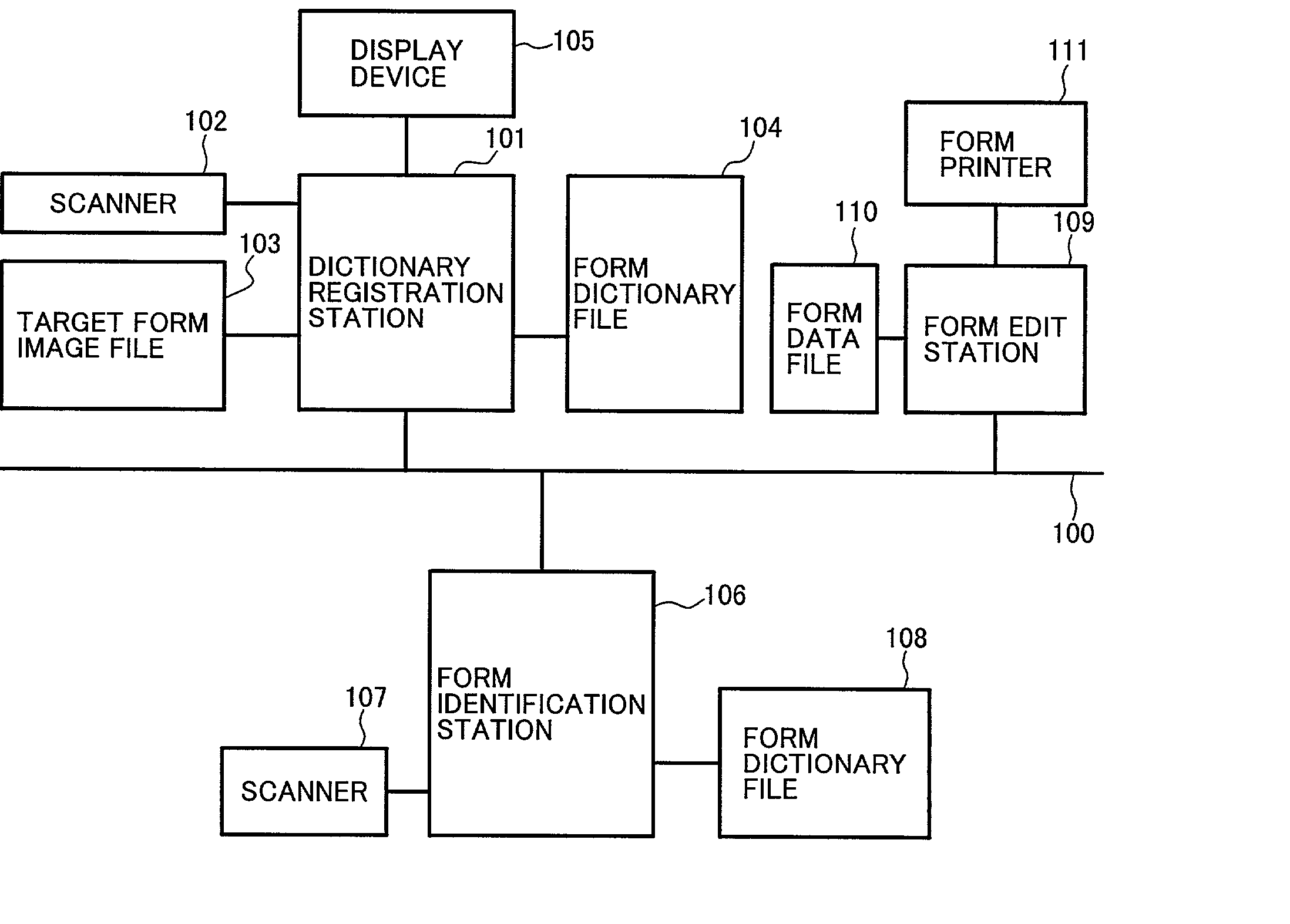
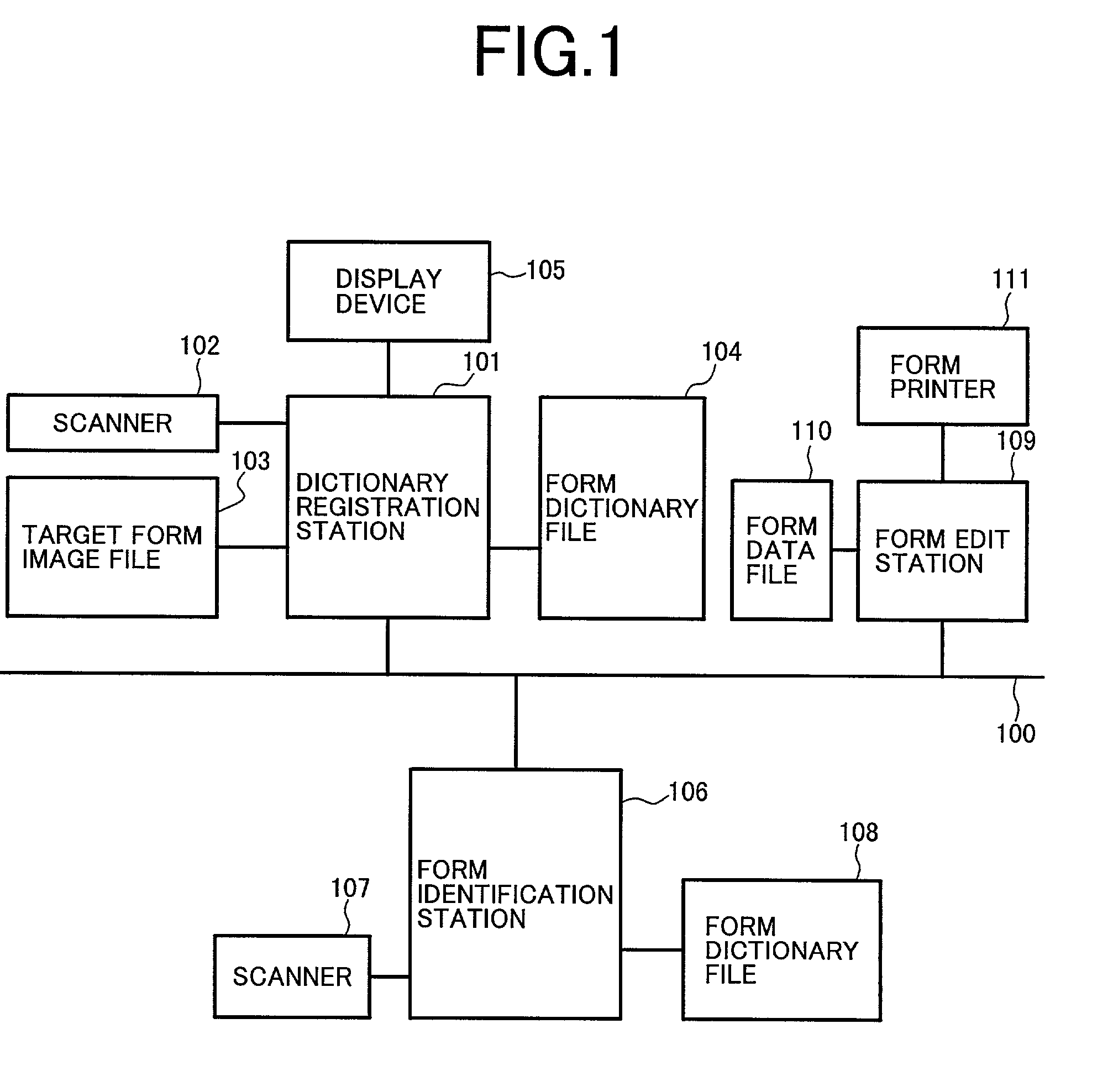
[0058] FIG. 1 is a block diagram showing an example of a construction of a form identification system for making a form identification and a form registration according to the embodiment of the invention. In FIG. 1, reference numeral 100 denotes a communication network; 101 a dictionary registration station; 102 and 107 scanners; 103 a registration target form image file; 104 and 108 form dictionary files; 105 a display device; 106 a form identification station; 109 a form edit station; 110 a form data file; and 111 a form printer.

[0059] The form identification system shown in FIG. 1 is constructed by connecting the dictionary registration station 101, form identification station 106, and form edit station 109 via the communication network 100, and those stations can mutually operate in an interlockin...


PUM


Abstract

A form identification method which can identify forms without errors even if a form is inputted from a scanner in different direction or the form is enlarged / shrunk. A form registration method which enables change / modification of forms when form types are pre-registered. Inputted points as features are extracted from the form, modification of enlargement / shrinkage, rotation, or skew is made to the inputted points. Form types are identified based on minimum distances between the inputted point and pre-registered dictionary points. When registering a similar form type, warning can be displayed on the screen. In a system a dictionary registration station, a form identification station, and a form edit station are connected via a communication network. Each station operates in interlocking manner, identifies inputted forms, and registers them into a dictionary.

Description

[0001] 1. Field of the Invention[0002] The invention relates to a form identification method of identifying a type of form which is read prior to processing of a form in case of reading a plurality of types of forms and a form registration method of registering the identified form. More particularly, the invention relates to a form identification method of enabling a type of form to be stably identified against the form direction, enlargement and shrinkage (or scale-up and scale-down), and skew of the form and to a form registration method.[0003] 2. Description of the Related Art[0004] As a conventional technique regarding a form identification method, there has been known a method whereby features for identifying the type of form, for example, character codes, character lines, lines or ruled lines, cells, and the like in the form are automatically extracted, the extracted features are subjected to matching with features of the form which have previously been registered on the basis...

Claims


Application Information

Patent Timeline
IPC IPC(8): G06K9/20G06K9/32G06Q10/10G06T7/00G06T7/60
CPCG06K9/00449G06V30/412
Inventor SHIMA, YOSHIHIRO
Owner HITACHI LTD
Learn More