Optical position determination on any surface

a technology of optical position determination and surface, applied in the field of optical position determination on any surface, can solve the problems of expensive tablets, difficult transportation, and the inability of tablets to distinguish between the stylus and another object pressing, and achieve the effect of accurate reading of passive coded surfaces

Inactive Publication Date: 2002-11-07
ANOTO AB
View PDF6 Cites 162 Cited by
  • Summary
  • Abstract
  • Description
  • Claims
  • Application Information

AI Technical Summary

Benefits of technology

0013] A significant advantage of the present invention is its interface. Overall, no matter how good a computer interface is, less of it would be better. The present invention allows for an interface that is almost identical to that of a pen / pencil and paper. The present invention is used in the same manner as a pen / pencil and paper and all of the computing is done in the background unnoticed by the user. The pen / pencil and paper are familiar and comfortable interfaces to the user.
0014] This inventor has patented a device (U.S. Pat. Nos. 5,477,012 and 5,852,434) comprising a passive coded surface and an active stylus comprising a video camera. The drawback to this system is the requirement of the passive coded surface. Availability of the passive coded surface and the ability of the active stylus to accurately read the passive coded surface are only some of the disadvantages of the patented device. The present invention overcomes these drawbacks by eliminating the need for the passive coded surface. Now, any surface can be used. For example, stylus and paper in the present invention will most closely simulate the familiar use of ordinary pen / pencil and paper.
0015] It is an object of the present invention to provide all of the aforementioned information.
0016] It is an object of the present invention to overcome all of the aforementioned disadvantages.
0017] It is an object of the present invention to provide an apparatus and method for obtaining and outputting the absolute position and / or movement of a moveable element on a surface.
0018] It is an object of the present invention to provide an apparatus and method for obtaining and outputting the absolute position and / or movement of a moveable element on a surface for acquisition and output of hand written data.

Problems solved by technology

The most significant is the active surface or tablet itself Besides being complex, large, heavy, cumbersome, and difficult to transport, the tablet is expensive.
Further, the tablet cannot usually distinguish between the stylus and another object pressing on it.
Still further, active tablets are difficult to manufacture, subject to interference from outside factors, and have complex mechanical and electrical parts that are subject to malfunction.
Most significantly, this method generally requires an awkward tablet besides a separate transmitter and receiver (usually in different locations).
Further, the transmitted signal can become obscured before reaching the receiver.
Both the passive stylus / active surface and active stylus / passive surface methods have the feeling of being unnatural and require a significant interface adjustment for the user from the conventional pen / pencil and paper.
The amount and accuracy of information provided by these methods are limited.
In addition, some of these methods require a physical connection between the stylus and the tablet.
The aforementioned methods can provide a printed hard copy, but they do not provide an original hard copy.
The drawback to this system is the requirement of the passive coded surface.
Availability of the passive coded surface and the ability of the active stylus to accurately read the passive coded surface are only some of the disadvantages of the patented device.

Method used


Image

  • Optical position determination on any surface
  • Optical position determination on any surface
  • Optical position determination on any surface

Examples


first embodiment

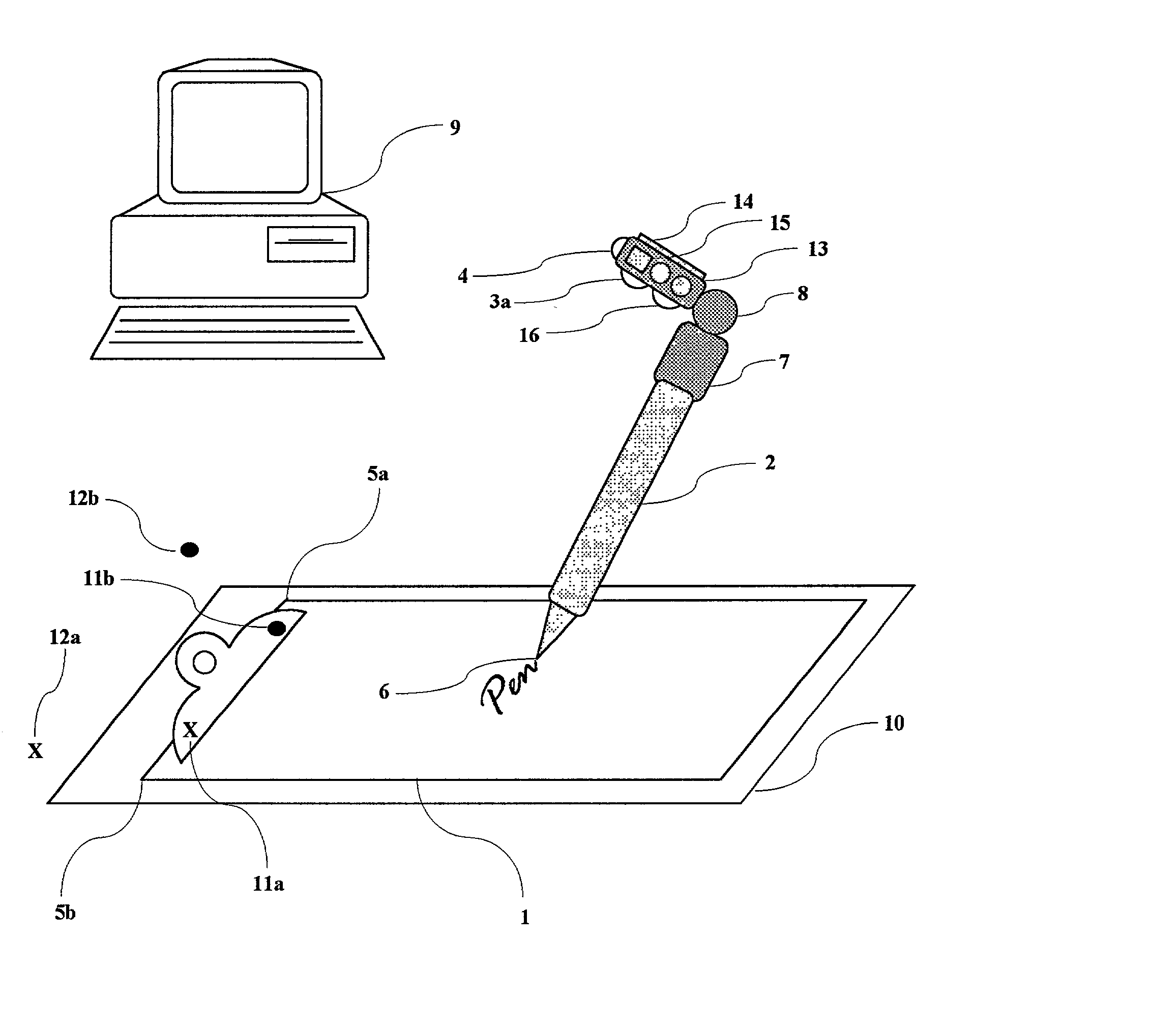
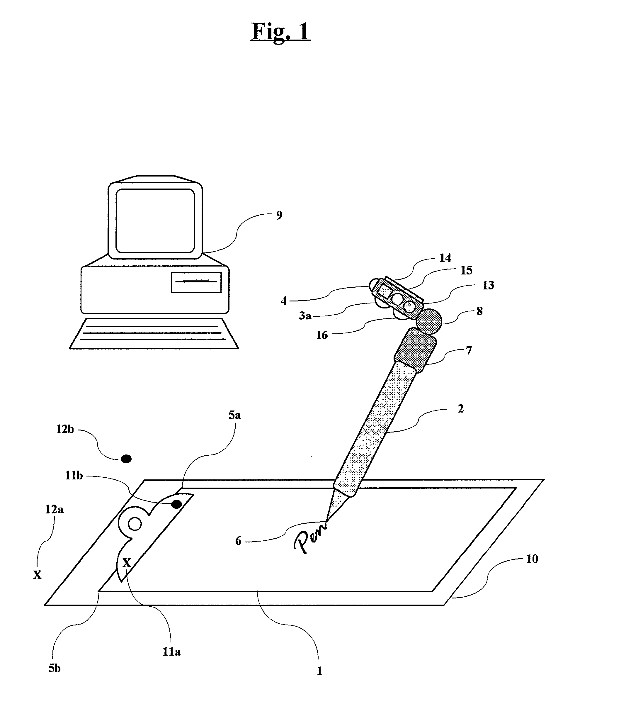
[0075] A first embodiment comprises a surface 1 in FIG. 1, a stylus 2, an upper digital camera 3a, and a wireless interface 4. The upper digital camera detects two fixed points based on a set of pre-determined criteria such as corners 5a and 5b of the surface and triangulates the instantaneous position of the writing element 6 of the pen. The two fixed points are dynamic, in that, the upper digital camera will detect any two points, which may include the corners of the surface, or any other points in its visual field. The other points may include pre-applied marks on the surface or marks instantly applied using the writing element. The upper digital camera may dynamically change the two fixed points it selects based on a set of pre-determined criteria.

[0076] The upper digital camera is mounted on the stylus 2 using an adapter 7 that fits securely on the upper end of the stylus. This position allows the upper digital camera to view the surface, the writing element, and the two fixed ...

second embodiment

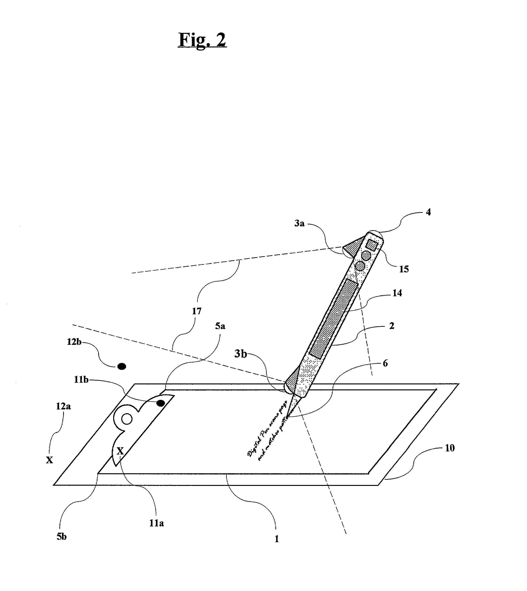
[0085] A second embodiment in FIG. 2 utilizes a second lower digital camera 3b mounted on the lower end of the stylus facing the same direction as the upper digital camera. The upper digital camera provides macro-triangulation, pattern-matching and / or position-related code and the lower digital camera provides micro-triangulation, pattern-matching and / or position-related code. The visual fields of the digital cameras are represented by 17 in FIG. 2.

third embodiment

[0086] A third embodiment in FIG. 3 comprises both the upper digital camera and lower digital camera mounted in opposite directions, whereby the upper digital camera uses macro-triangulation, pattern-matching and / or position-related code and the lower digital camera uses micro-triangulation, pattern-matching and / or position-related code. The visual fields of the digital cameras are represented by 17 in FIG. 3. These techniques combined provide high-resolution data regarding information on the surface and movement of the stylus over the surface.

[0087] A fourth embodiment in FIG. 4 comprises a lower digital camera 3b mounted away from the user. A fifth embodiment in FIG. 5 comprises an upper digital camera 3a and a lower sensor 6b. The lower sensor can be in the form of a trackball, pressure sensor, transducer, gyroscope, and / or accelerometer located in the stylus itself, whereby the upper digital camera uses macro-triangulation, micro-triangulation, pattern-matching and / or position-r...


PUM


Abstract

The present invention proposes the use of a surface or writing surface such as paper and a moveable element such as a pen or a stylus. The stylus comprises an input means such as a charge-coupled device (CCD) or digital camera, a microcomputer, memory, power supply, and a communications device, whereby the digital camera scans the surface for position-related information to determine the position and/or movement of the stylus relative to the surface. The path of stylus is determined by detecting a sequence of position-related information. An output signal from the digital camera or array of light sensitive elements is sent to a computer or processor and finally output to the user. The output can be in various forms including an image on a computer display or a computer printout. When writing on the surface, handwriting recognition software can be used to convert the handwritten text into a "keyboard-typed" representation.

Description

[0001] This application is a continuation in part and claims the benefit under 35 USC 120 of U.S. patent application Ser. No. 09 / 725,301 filed Nov. 29, 2000 and U.S. patent application Ser. No. 09 / 725,883 filed Mar. 9, 2001. Previous disclosure was made in Disclosure Document No. 492507 filed Apr. 5, 2001 and PCT Application No. PCT / USO1 / 44854 filed Nov. 29, 2001. This invention relates to an apparatus and method for generating position-related computer data by obtaining and outputting the instantaneous position and / or movement of a moveable element on a surface, such as might be used for determining the position and / or movement of a pen / pencil on paper. In addition, this invention will allow the user to input graphical information (e.g., images, drawings or handwriting) and simultaneously provide an original hard copy of the information.BACKGROUND-DESCRIPTION OF PRIOR ART[0002] The following United State Patents are believed to be most closely related to the present invention:[0003...

Claims


Application Information

Patent Timeline
Patent Type & Authority Applications(United States)
IPC IPC(8): G06F3/033G06F3/042
CPCG06F3/0321G06F3/03545G06F3/03542G06F3/0325
Inventor SEKENDUR, ORAL FAITH
Owner ANOTO AB
Why Eureka
Try Eureka