Method and system for locking transmission wavelengths for lasers in a dense wavelength division multiplexer

a technology of dense wavelength division multiplexers and lasers, applied in semiconductor lasers, instruments, optics, etc., can solve the problems of difficult and time-consuming process, requiring skilled technicians, and the calibration of all forty dfb lasers of a single dwdm can be quite expensive, and the cost of maintaining a set of dwdms is often substantial

Inactive Publication Date: 2002-11-07
SPECTRASENSORS INC
View PDF1 Cites 25 Cited by
  • Summary
  • Abstract
  • Description
  • Claims
  • Application Information

AI Technical Summary

Benefits of technology

[0058] Two resistive heating elements 632 and 634 (not shown) made of nickel chromium are vapor deposited or mounted on opposing sides of the etalon. Each resistive heating element has a pair of gold contacts 636 on opposing ends thereof for coupling to electrical leads (not shown) from the wavelength-locking controller 628 (FIG. 11). The etalon is selectively heated by the wavelength-locking controller by applying current through the resistive leads by an amount sufficient to expand or contract the optical axis of the etalon to change its index of refraction and to align one of the transmission lines of the etalon with the selected ITU channel. With the parameters mentioned above, any C-band ITU channel can be accommodated by adjusting the temperature of the etalon in the range of approximately 72.+-.2 degrees C. No TE cooler or other cooling components are required. Rather, cooling is achieved by allowing the etalon to slowly lose heat to the ambient environment. In the alternative, rather than using resistive heating elements to vary the length of the entire etalon, a reflective micro-electrical mechanical system (MEMS) membrane may be mounted to an end of the etalon and coupled to the wavelength-locking controller to permit the controller to adjust an optical reflecting path of the etalon to thereby adjust the wavelengths of the transmission lines of the etalon.

Problems solved by technology

This is a difficult and time-consuming process requiring skilled technicians.
Calibration of all forty DFB lasers of a single DWDM can be quite expensive.
Mechanical or thermal drift of the etalon over time often moves the transmission peak away from the target ITU channel, which requires recalibration.
As a result, the cost of maintaining a set of DWDMs is often substantial.
However, the WTL cannot simply and accurately be tuned to any target ITU channel at a customer installation and must be calibrated at the factory for operation at a specific channel.
Another problem associated with employing DFB lasers within DWDMs is that, because each DFB laser can only be tuned within a narrow range of about 2 nm, each DFB laser can only be calibrated to one of a few adjacent ITU transmission wavelength lines.
Although the use of WTLs remedies many of the problems associated with using DFB lasers, WTLs are difficult and expensive to fabricate and initially calibrate, and are susceptible to wavelength drift requiring frequent recalibration at the customers installation by trained technicians and hence necessitating high overall installation and maintenance costs.
Thus, whether using DFB lasers or WTLs within a DWDM, significant problems arising in achieving and maintaining proper wavelength calibration of the lasers to permit reliable operation of the DWDM.
Difficulties arise in each of these areas.
Using numerous closely spaced peaks, however, increases the risk that the wavelength locker will lock the transmission wavelength of the WTL to the wrong wavelength.
Also, to provide numerous closely-spaced transmission peaks, the etalon typically must be configured to have a very short optical axis, thereby making it more difficult to fabricate and align.
Moreover, difficulties arise in adequately insulating the temperature-controlled etalon so as to minimize power loss and to ensure a minimal temperature gradient within the etalon.
Any significant temperature gradient within the etalon tends to degrade the finesse of the etalon (i.e. the sharpness of the individual etalon lines) thus making it difficult to achieve precise wavelength locking.
Likewise, any slight misalignment of the etalon or any slight imprecision in reflection coatings of the etalon reduces the degree of finesses.
Lack of adequate insulation, of course, also increases power consumption and generates a greater amount of waste heat, which may affect the ability of the TE cooler of the laser to efficiently control the temperature of the laser, particularly if the etalon is mounted closely adjacent to the laser within the butterfly package.
Typically, manufacturing protocols for DWDMs specify that the DWDM must operate at 70 degrees Celsius or less, thus putting further limitations on the design of the temperature-controlled etalon.
It is difficult, therefore, to provide a temperature-controlled etalon and other wavelength locker, which achieves the requisite degree of finesse for precise wavelength locking while also minimizing power consumption, even for use with just one ITU channel protocol.
Yet the etalon is not so small as to make fabrication and alignment of the etalon difficult, or to require the length of the etalon to be sufficiently short so that the spacing between transmission fringes is too great for efficient use, particularly with ITU protocols having widely-spaced grid lines.

Method used


Image

  • Method and system for locking transmission wavelengths for lasers in a dense wavelength division multiplexer
  • Method and system for locking transmission wavelengths for lasers in a dense wavelength division multiplexer
  • Method and system for locking transmission wavelengths for lasers in a dense wavelength division multiplexer

Examples


Embodiment Construction

[0037] With reference to the remaining figures, exemplary embodiments of the invention will now be described.

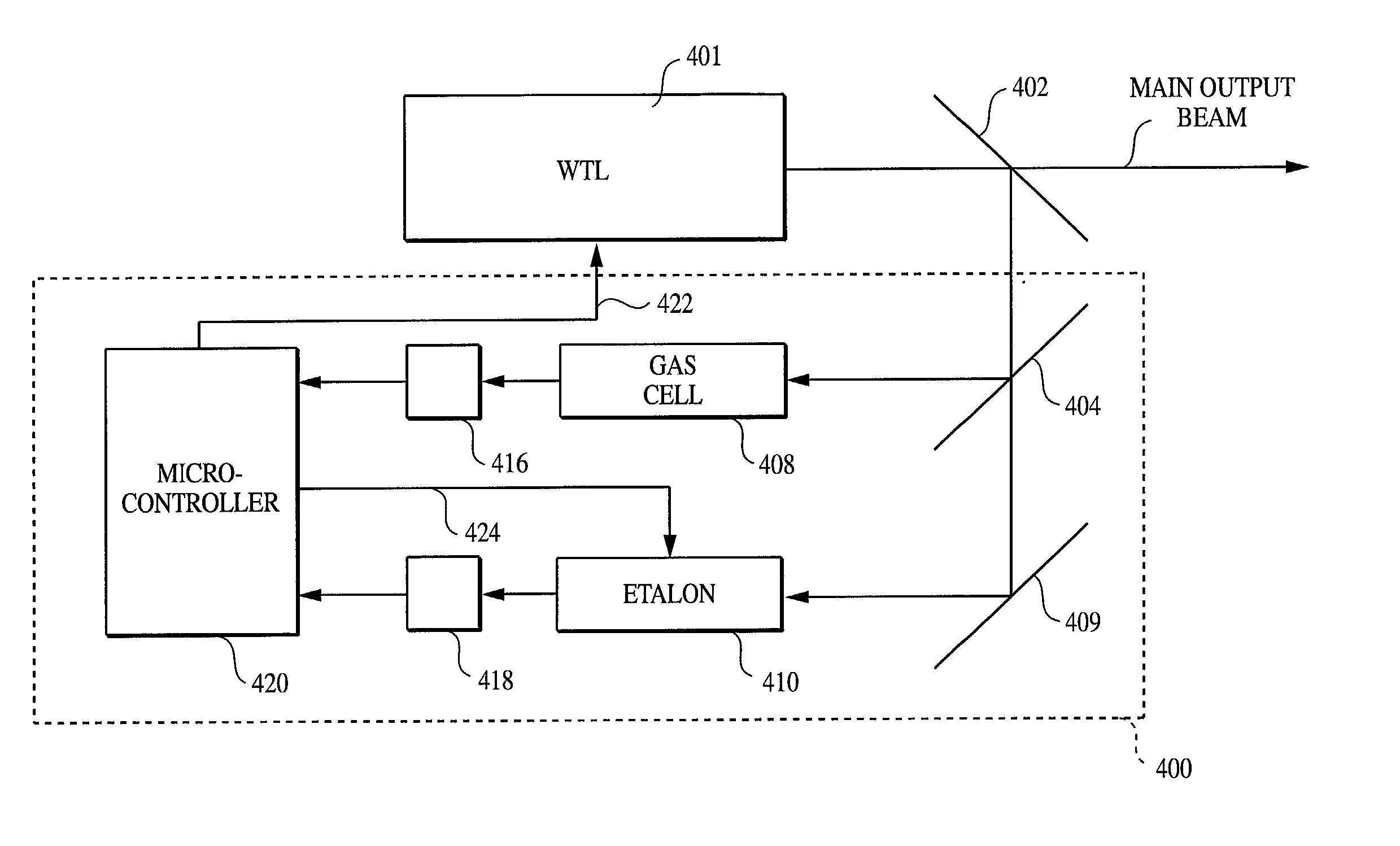
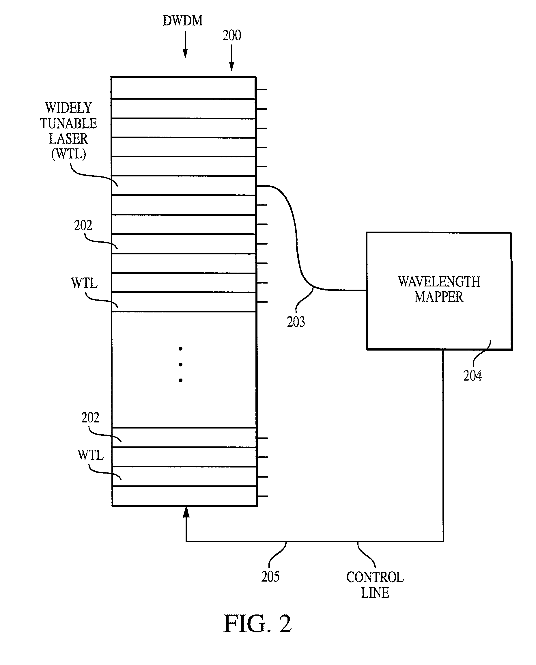
[0038] FIG. 2 illustrates a DWDM 200 having forty individual WTLs 202 for transmitting optical signals on forty ITU C-band channels via a single optic fiber (not shown). In FIG. 2, an optic fiber output from a selected WTL is connected via a fiber optic line 203 to the input of a hand-held, portable wavelength mapper 204 configured for automatically determining the transmission wavelength of the WTL as a function of WTL tuning parameters, such as a WTL control voltage or current, output from the wavelength mapper to the selected WTL of DWDM via a control line 205. Although a forty channel DWDM is shown, in other implementations 80, 160, or more WTLs are provided. Also, other lasers may be employed in the alternative, such as DFB lasers, provided their tuning range is sufficient to record a minimum number of gas absorption lines (.gtoreq.5).

[0039] To permit the DWDM to transmi...


PUM

PropertyMeasurementUnit
optical axis lengthaaaaaaaaaa
lengthaaaaaaaaaa
optical axis lengthaaaaaaaaaa

Abstract

The method and system operate to calibrate a transmission laser of the dense wavelength division multiplexer (DWDM) and to lock the laser to a selected transmission wavelength. In one example, the transmission laser is a widely tunable laser (WTL) to be tuned to one of a set of International Telecommunications Union (ITU) transmission grid lines for transmission through an optic fiber. To lock the WTL to an ITU grid line, a portion of the output beam from the WTL is routed through the etalon to split the beam into a set of transmission lines for detection by a detector. Another portion of the beam is routed directly to another detector. A wavelength-locking controller compares signals from the two detectors and adjusts the temperature of the etalon to align the wavelength of one of the transmission lines of the etalon with the wavelength of the output beam, then controls the WTL in a feedback loop to lock the laser to the etalon line. The wavelength-locking controller thereafter monitors the temperature of the etalon and keeps the temperature constant to prevent any wavelength drift in the etalon. In one example, the etalon is a silicon etalon configured to have finesse of about 20 and to provide a free spectral range of about 8 GHz. With these parameters, the system is able to lock the wavelength of the WTL to within a precision of about 0.2 GHz.

Description

[0001] This patent application is a Continuation-in-Part of U.S. patent application Ser. No. 09 / 685,212, of Randy May entitled "Method And Apparatus For Determining Transmission Wavelengths For Lasers In A Dense Wavelength Division Multiplexer", filed Oct. 10, 2000.[0002] 1. Field of the Invention[0003] The invention generally relates to dense wavelength division multiplexers (DWDM) and in particular to a technique for locking transmission wavelengths of individual lasers of the DWDM.[0004] 2. Description of the Related Art[0005] A DWDM is a device for simultaneously transmitting a set of discrete information channels over a single fiber optic transmission line. A conventional fiber optic transmission line is capable of reliably transmitting signals within a bandwidth of 1280 to 1625 nanometers (nm), the "low loss" region for silica fiber. Within that overall bandwidth, the International Telecommunications Union (ITU) has defined various transmission bands and specified certain tran...

Claims


Application Information

Patent Timeline
Patent Type & Authority Applications(United States)
IPC IPC(8): G02F1/01H01S3/13H01S5/06H01S5/0687H01S5/40
CPCH01S3/1303H01S5/4087H01S5/0687H01S5/0617
Inventor MAY, RANDY DEAN
Owner SPECTRASENSORS INC
Why Eureka
Try Eureka