Shear retort for ablative pyrolysis

a pyrolysis and ablative technology, applied in the field of pyrolysis reactors, calcination or ore processing, can solve the problems of harmful emissions, waste of valuable hydrocarbon products, and expensive separate drying steps

Active Publication Date: 2020-03-31
VORSANA INC
View PDF14 Cites 0 Cited by
  • Summary
  • Abstract
  • Description
  • Claims
  • Application Information

AI Technical Summary

Benefits of technology

[0008]The motion of the spinning disk and the pressure of the incoming feed will force it into the pyrolysis zone of the workspace, and make the hot pyrolyzed solids material be continuously extruded from the edge of the disk, and accumulate in the drum storage space in the interior of the drum. As this accumulated material level rises in the drum, it will also cover the upper surface of the rotating disk within the drum. This covering layer keeps the rotating disk hot, both by direct transfer of heat from the hot material, and also by heat insulation to prevent the disk from losing heat. After the optimal level of solids in the drum is reached, the excess product is continuously extruded from the drum. The final product extrusion is allowed to cool until it no longer poses a threat for fire or explosion when exposed to oxygen.
[0009]A motor drives the rotation of the disk, and that rotation can be transferred by pressure and friction to cause the motion of a rotating drum, in the manner of a clutch. A brake mechanism is used to partially arrest the rotation of the rotating drum, so that there is a difference of rotation speed between the disk and the drum. This difference of rotation speed produces shear and friction, which is intended to be the primary cause of the heat for pyrolysis. Supplemental heating, such as from burners underneath the drum, or electrical resistance elements built into the disk or drum, can also help establish and maintain the best pyrolysis temperature, in combination with the friction heating. Supplemental cooling such as from water lines incorporated into the disk or drum, can also be used to lower the temperature of the workspace. Special sacrificial wear plates can be built into the disk and drum at the shear surfaces to allow for easy maintenance replacements.

Problems solved by technology

However, commercial methods have focused on fast pyrolysis, which produces more oil, often of sub-optimal quality, and requires expensive separate drying steps, and methods to separate the solids from the gaseous products.
This causes harmful emissions, and also wastes a valuable hydrocarbon product.
However, this shear retort design does not detail how the management of the extrusion of the pyrolyzed material at the disk edges can be used to reuse the heat for pyrolysis, or how an indirect drive method for one of the disk surfaces can be moderated by a brake.
The existing design also does not include the enclosure of the extruded material, to retain heat and fumes and prevent fires from the premature exposure of the hot material to oxygen.
This design also does not address the issues involved with the feed coming in from the top of the device, including how to keep the exhaust gas stream separated from the incoming feed stream.

Method used


Image

  • Shear retort for ablative pyrolysis
  • Shear retort for ablative pyrolysis
  • Shear retort for ablative pyrolysis

Examples


Embodiment Construction

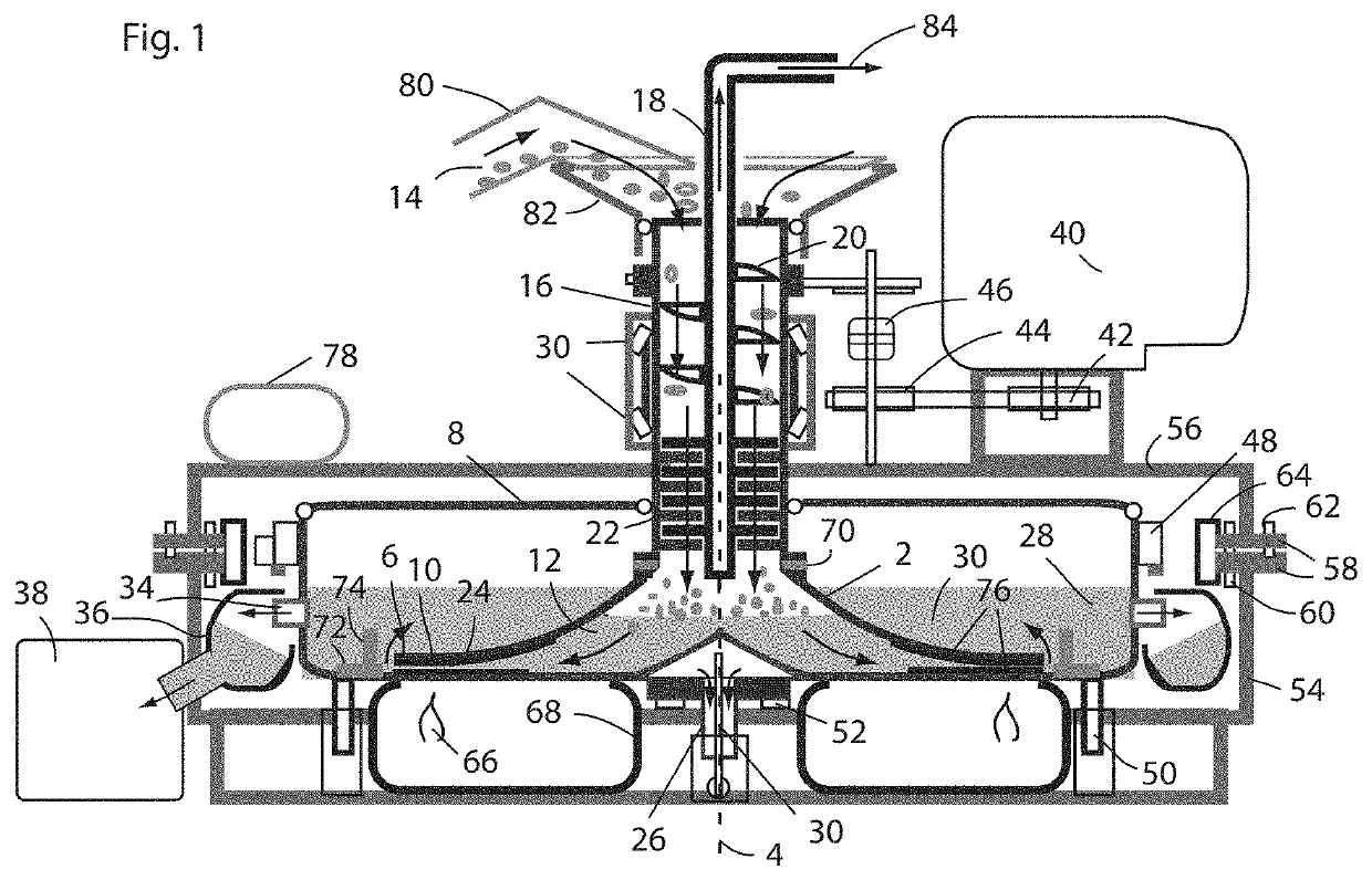
[0016]The shear retort processor here shown in FIG. 1 includes a rotating disk 2 with a conical flared cross section centered on an axis of rotation 4. The flare shape of the disk increasingly flattens in profile as it extends toward the periphery of the disk 6, where it is especially close to an enclosing drum 8, which is shown here as having a flat bottom. This close distance 10 is where there the maximum shear and grinding on the feed will take place. If the closest shear surfaces on the disk and drum are parallel, then there will be a region with this close distance where the maximum shear will take place.

[0017]A workspace 12 is defined by the space between the rotating disk 2 and the bottom of the drum 8, extending radially from the axis of rotation 4 to the disk periphery. A feed 14 enters the workspace 12 through a rotating hollow feed shaft 16 coupled to the rotating disk 2. A static exhaust pipe 18 is centered on the axis of rotation 4 at the center of the feed shaft 16 and...


PUM

PropertyMeasurementUnit
rotationaaaaaaaaaa
particle sizeaaaaaaaaaa
temperatureaaaaaaaaaa

Abstract

A shear retort mill for slow ablative pyrolysis features friction heating between shearing surfaces on a rotating disk and a static or rotating cylindrical drum enclosing the disk. A feed enters the workspace between the rotating disk and the bottom of the drum through a hollow feed shaft coupled to the rotating disk. Preferably, an auger compacts and moves the feed downward, and a shredder reduces the feed's particle size. The feed is increasingly ground and pyrolyzed as it is forced between the drum and disk shearing surface. As the dense processed material extrudes at the edge of the workspace, the gases and liquid products are forced inward by the barrier of dense solids. A static exhaust pipe at the center of the rotating feed shaft allows for the exit of these gases, which preferably go to a heat exchanger to recover any condensable fractions.

Description

FIELD OF INVENTION[0001]The present invention relates to milling equipment, and to reactors for pyrolysis, calcination, or ore processing, especially when gaseous or liquid fractions are recovered from the ground material.BACKGROUND OF THE INVENTION[0002]The transformation of material by heating, especially in the absence of oxygen, is called pyrolysis. Pyrolyzed wood, for example, produces biochar, which is a useful material both for increasing soil fertility and also burying excess carbon. However, commercial methods have focused on fast pyrolysis, which produces more oil, often of sub-optimal quality, and requires expensive separate drying steps, and methods to separate the solids from the gaseous products. Other smaller scaler methods feature the burning of the hydrocarbon fumes from the pyrolysis in order to generate the required heat. This causes harmful emissions, and also wastes a valuable hydrocarbon product.[0003]Disk mills have long been used to grind material to smaller ...

Claims


Application Information

Patent Timeline
Patent Type & Authority Patents(United States)
IPC IPC(8): C10B1/00B01D45/16C10B27/00C10B1/10B01J8/08C10B57/00B03C3/00B01J8/00
CPCB03C3/00B01J8/08B01D45/16C10B1/10C10B27/00B01J8/087B01J8/008C10B57/00B01J2208/00769C10B1/00B03C3/017C10B47/34C10B53/00C10B53/02C10K1/026C10K1/04Y02E50/10
Inventor MCCUTCHEN, DAVID J.
Owner VORSANA INC
Why Eureka
Try Eureka