
Optical medical instrument

a medical instrument and optical technology, applied in the field of optical medical instruments, to achieve the effect of improving the environment of the instrument and removing the loss of hea

Active Publication Date: 2017-09-12
KARL STORZ GMBH & CO KG
View PDF7 Cites 1 Cited by
  • Summary
  • Abstract
  • Description
  • Claims
  • Application Information

AI Technical Summary

Benefits of technology

[0011]It is an object of the invention to provide an optical medical instrument in which the removal of lost heat to the environment of the instrument is improved.
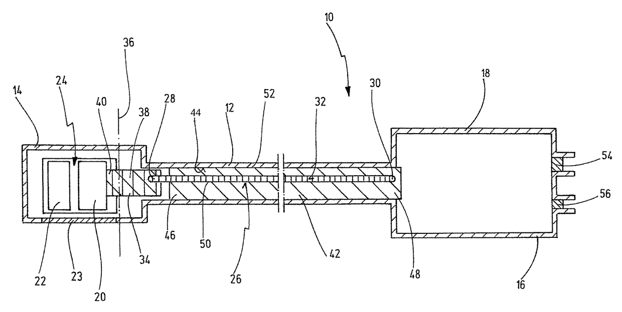
[0013]In contrast to the prior art, the present invention uses the shaft of the instrument for heat transfer to the environment, and not just in punctiform fashion, but over a large surface area. Therefore, in the instrument according to the invention, the shaft of the instrument itself is used as a heat sink. Moreover, in the prior art, it was assumed that a heat pipe can only collect heat at one end and release heat at the opposite end. However, in the context of the invention, it has been found that a heat pipe can also release heat between its two ends. If, as is provided for according to the invention, the whole shaft of the instrument, or at least a large area of the shaft, is used as a heat sink, the heat dissipated from the heat source will be released by the heat pipe precisely at the location where the shaft is at its coldest. The greater the area and the surface of the thermally conductive coupling between the heat pipe and the shaft, the greater the number of places at which the heat sink can be located along the heat pipe and the shaft, sometimes all the way along the heat pipe. Therefore, according to the function of the heat pipes, the position of the heat sink is automatically established “flexibly” along the shaft. This concept according to the invention is referred to hereinbelow as a “flexible heat sink”. The concept of the “flexible heat sink” ensures that the heat is distributed relatively uniformly across the existing surface of the shaft and, as a result, temperature differences are kept as low as possible. Advantageously, local temperature peaks and therefore high temperature gradients along the shaft are at least reduced or even avoided in this way. The lost heat is instead transferred uniformly from the heat pipe to the shaft and from the latter to the environment. The danger of the shaft heating to a temperature above the maximum limit of 41° C. allowed by the Medical Devices Act is therefore likewise avoided. The heat removal in the instrument according to the invention is also very efficient, since the heat transfer takes place across a large surface area of the shaft.
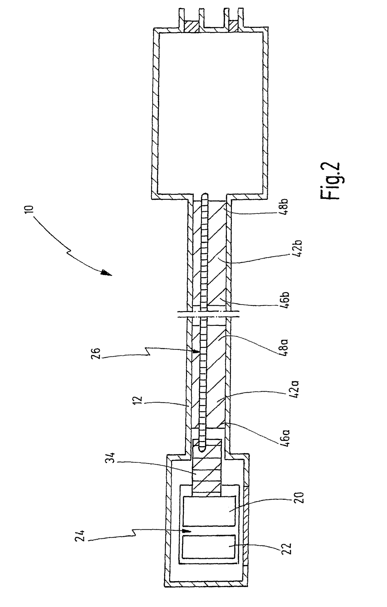
[0020]An important factor regarding the efficacy of the heat removal management system according to the invention is the thermally conductive connection of the heat pipe to the shaft over a surface area that is as large as possible, whether it be the direct connection of the heat pipe to the inner face of the shaft or, alternatively or in addition, the connection via one or more heat sink bodies. The form fit between the heat pipe and the inner face of the shaft in a direct thermally conductive coupling and the form fit between the heat sink body and the heat pipe, on the one hand, and between the heat sink body and the inner face of the shaft, on the other hand, in the case of an indirect thermally conductive coupling of the heat pipe to the shaft, improve the thermal connection of the heat pipe to the shaft.
[0023]Compared to a coupling between heat pipe and heat source based on heat radiation or convection, the thermally conductive coupling has the advantage of a more effective heat transfer from the heat source to the heat pipe, particularly if the connection of the heat pipe to the heat coupling element is made with a form fit.
[0025]By pressing the heat pipe into the heat coupling element, a form fit connection between the heat pipe and the heat coupling element is produced in a simple manner, and the heat pipe can also be deformed in cross section by being pressed in.
[0026]To avoid an excessive deformation of the heat pipe, which can impair the inner capillary action of the heat pipe, the form-fit connection of the heat pipe to the heat coupling element can also be additionally fixed by means of a thermally conductive joining material.

Problems solved by technology

Moreover, in the prior art, it was assumed that a heat pipe can only collect heat at one end and release heat at the opposite end.

Method used


Image

  • Optical medical instrument
  • Optical medical instrument
  • Optical medical instrument

Examples


Embodiment Construction

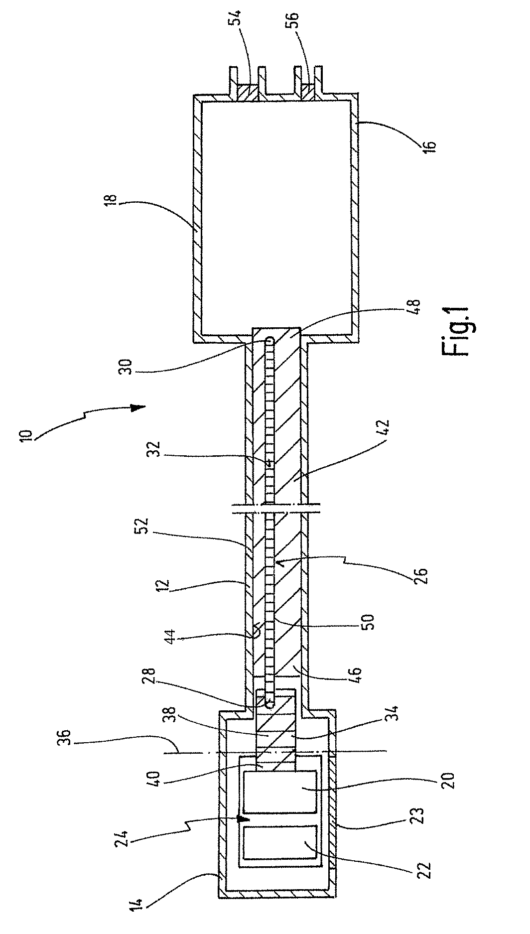
[0060]FIG. 1 shows an optical medical instrument 10 in a schematic view. The instrument 10 is an endoscope or an exoscope.

[0061]Generally, the instrument 10 has an elongate tubular shaft 12 between a distal end 14 and a proximal end 16. The shaft 12 is depicted in an interrupted view in order to show that the shaft 12 can extend over a great length. In FIG. 1, the distal end area of the instrument 10 and the proximal end area of the instrument 10 are also shown as being wider, although this is to be understood only by way of example. The proximal end 16 is designed here as an instrument head housing 18. The shaft 12 and the instrument head housing 18 constitute the housing for the components located therein. The instrument head housing 18 can belong to the shaft 12. Likewise, the shaft 12 itself is to be understood as a housing. The housing can be hermetically sealed.

[0062]The components in the shaft 12 include electronic elements arranged in the distal end area of the shaft 12, suc...


PUM


Abstract

An optical medical instrument, in particular an endoscope or exoscope, has an elongate tubular shaft, a heat source generating lost heat, and a heat pipe which extends inside the shaft, in the longitudinal direction of the shaft, and has a distal heat pipe end and a proximal heat pipe end, wherein the heat pipe is thermally coupled to the heat source in order to collect heat from the latter and remove the heat from the heat source. Between the distal heat pipe end and the proximal heat pipe end, the heat pipe is coupled thermally conductively and two-dimensionally to the shaft over at least a partial length of the heat pipe and over at least a partial circumference of the heat pipe, in order to remove heat from the heat pipe, over at least a partial length and over at least a partial circumference of the shaft, to the environment.

Description

CROSS REFERENCE TO RELATED APPLICATIONS[0001]The present application claims priority of German patent application No. 10 2014 107 205.7 filed on May 22, 2014, the whole contents of which is incorporated herein by reference.BACKGROUND OF THE INVENTION[0002]The invention relates to an optical medical instrument, in particular an endoscope or exoscope. In particular, the invention relates to an optical medical instrument of the type comprising an elongate tubular shaft, a heat source generating lost heat, a heat pipe extending inside the shaft in the longitudinal direction of the shaft and having a distal heat pipe end and a proximal heat pipe end, wherein the heat pipe is thermally coupled to the heat source in order to collect heat from the latter and remove the heat from the heat source.[0003]Endoscopes are used in the context of minimally invasive surgery as viewing instruments. The elongate shaft of an endoscope is inserted partially into the body through an artificially created o...

Claims


Application Information

Patent Timeline
Patent Type & Authority Patents(United States)
IPC IPC(8): A61B1/12A61B1/00A61B1/06G02B23/24
CPCA61B1/128A61B1/00071A61B1/00128A61B1/0676G02B23/2476A61B1/0684G02B23/2461
Inventor PILZ, KEVINKUPFERSCHMID, MARKUSULMSCHNEIDER, DANIELHENI, ANDREAS
Owner KARL STORZ GMBH & CO KG
Learn More