Electrochemical storage device having improved electrical conduction properties

a technology of electrical conduction and electrochemical storage, which is applied in the direction of non-aqueous electrolyte cells, batteries, cell components, etc., can solve the problems of reducing the overall electrical efficiency of individual electrochemical storage devices by up to several percentage points in comparison with regular operation, and affecting the overall electrical efficiency of individual electrochemical storage devices. , the effect of reducing the overall electrical efficiency of individual electrochemical storage devices

Active Publication Date: 2015-12-03
SIEMENS ENERGY GLOBAL GMBH & CO KG
View PDF3 Cites 0 Cited by
  • Summary
  • Abstract
  • Description
  • Claims
  • Application Information

AI Technical Summary

Benefits of technology

[0012]An object of the present invention is accordingly to propose an electrochemical storage device which avoids the disadvantages known from the prior art. The electrochemical storage device proposed according to the invention is intended in particular to allow operation also at high current densities, wherein the ohmic power loss is however intended to be reduced in comparison with conventional storage devices. In particular, it is intended to propose improving a storage device in terms of energy lost as heat through a simple, inexpensive structural modification to electrochemical storage devices known from the prior art. The improved current conduction behavior is intended in particular to relate to the conduction behavior of the anode.

Problems solved by technology

In the case of high power storage devices in particular, relatively significant heat production may arise in these regions due to the ohmic losses.
However, this puts at risk reliable operation of such thermal modules and additionally brings about a reduction in the overall electrical efficiency of individual electrochemical storage devices of up to several percentage points in comparison with regular operation.
However, if the electrochemical storage devices are exposed to very high local current densities and operated at the limits of their design, power losses of several watts may occur.

Method used


Image

  • Electrochemical storage device having improved electrical conduction properties
  • Electrochemical storage device having improved electrical conduction properties
  • Electrochemical storage device having improved electrical conduction properties

Examples


Embodiment Construction

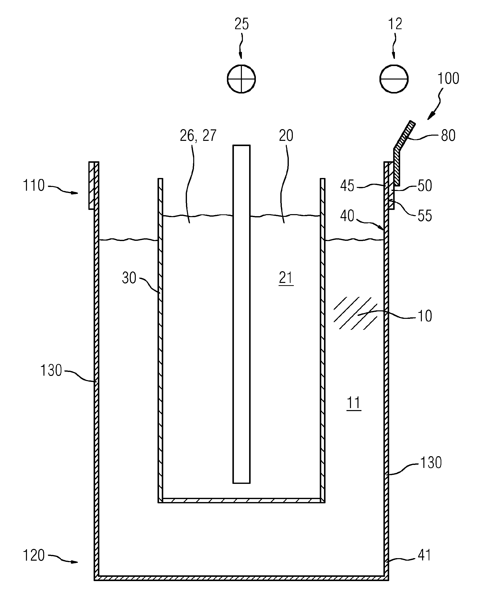
[0051]FIG. 1 shows a lateral sectional view through a first embodiment of an electrochemical storage device 100 according to the invention, which has an anode compartment 11 separated from a cathode compartment 21 by a solid electrolyte 30. In a typical operating state as shown here, the anode compartment 11 is filled with anode material 10. The cathode compartment 21 is likewise filled with cathode material 20. The solid electrolyte 30 is here of can-shaped construction.

[0052]According to sodium-nickel chloride cell technology, the anode material is elemental sodium which assumes liquid form at the operating temperature of the storage device 100 (for instance between 200° C. and 350° C.).

[0053]The filling level of the liquid content of cathode material 20 in the cathode compartment 21 correlates, depending on the state of charge of the electrochemical storage device 100, with the filling level of the anode compartment 11. In the present case, the cathode material 20 in particular c...


PUM

PropertyMeasurementUnit
operating temperatureaaaaaaaaaa

Abstract

An electrochemical storage device has an anode chamber filled with anode material during operation, and a cathode chamber filled with cathode material. The anode chamber is separated from the cathode chamber by solid body electrolyte guiding ions, and the anode chamber is limited on one side by the solid body electrolyte, on another side by a wall at least partially surrounding the solid body electrolyte. The wall is surrounded by a head part of the device, by a base part arranged opposite the head part and/or by a lateral part arranged between the head and base part. The wall has an electrical conductive wall section as an anode to the anode chamber, an at least partially flat, electrical conductive line section electrically connected to the wall section by a surface, and conductivity per surface of the line section greater than conductivity of the wall per surface of the wall section.

Description

CROSS REFERENCE TO RELATED APPLICATIONS[0001]This application is the US National Stage of International Application No. PCT / EP2013 / 077394 filed 19 Dec. 2013, and claims the benefit thereof. The International Application claims the benefit of European Application No. EP13150509 filed 8 Jan. 2013. All of the applications are incorporated by reference herein in their entirety.FIELD OF INVENTION[0002]The present invention relates to an electrochemical storage device which has an anode compartment filled with an anode material and a cathode compartment filled with a cathode material, wherein the anode compartment is separated from the cathode compartment by an ion-conductive solid electrolyte, and wherein the anode compartment is delimited on one side at least in part by the solid electrolyte and on another side at least in part by a wall which at least in part surrounds the solid electrolyte, which wall is comprised by a top part of the electrochemical storage device, a bottom part arra...

Claims


Application Information

Patent Timeline
Patent Type & Authority Applications(United States)
IPC IPC(8): H01M10/39H01M2/26H01M50/516H01M50/522H01M50/528H01M50/531
CPCH01M10/39H01M2220/30H01M2/26H01M10/3981H01M10/3909Y02E60/10H01M50/138H01M50/528H01M50/522H01M50/516H01M50/531
Inventor KUHNE, MICHAEL
Owner SIEMENS ENERGY GLOBAL GMBH & CO KG
Why Eureka
Try Eureka